
Magnetic memory devices and methods of writing data to the same

Active Publication Date: 2014-09-18
SAMSUNG ELECTRONICS CO LTD
View PDF5 Cites 23 Cited by
  • Summary
  • Abstract
  • Description
  • Claims
  • Application Information

AI Technical Summary

Benefits of technology

The patent describes magnetic memory devices that use a spin Hall effect to switch magnetoresistive cells. The devices include a bit line with a spin Hall effect material layer and a lower electrode. The direction of the current in the bit line is parallel to the free layer, which has a variable magnetization direction. The devices also include a pinned layer with a fixed magnetization direction. The direction of the current in the pinned layer is perpendicular to the free layer. The devices can switch data using a spin Hall effect and a spin transfer torque created by a second current that passes through the pinned layer to the free layer. The method of writing data involves applying a first current to the bit line and a second current to the free layer simultaneously. The first and second currents start with a time delay and end with another time delay. The devices and methods described provide improved performance and reliability for magnetic memory devices.

Problems solved by technology

Furthermore, a switching method called toggle switching may significantly reduce writing errors.
However, when the size of a unit cell is reduced to implement a high density memory device, a switching field increases with an increase of the coercivity of a free layer, thereby resulting in an increase in amplitude of applied current.
Furthermore, in a memory cell array having a plurality of memory cells, switching may occur even in a free layer in an inappropriate cell.
Thus, a magnetic memory device employing switching induced by Oersted fields may have difficulty in achieving selectivity and high density.
However, STT-MRAM does not allow toggle switching, and providing a margin for reducing writing errors becomes a key issue for the STT-MRAM.

Method used


Image

  • Magnetic memory devices and methods of writing data to the same
  • Magnetic memory devices and methods of writing data to the same
  • Magnetic memory devices and methods of writing data to the same

Examples


Embodiment Construction

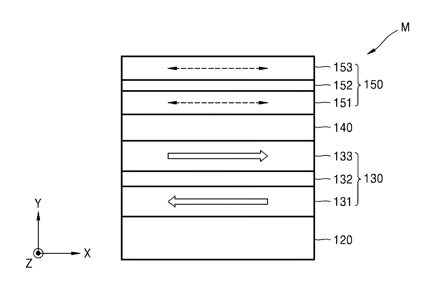
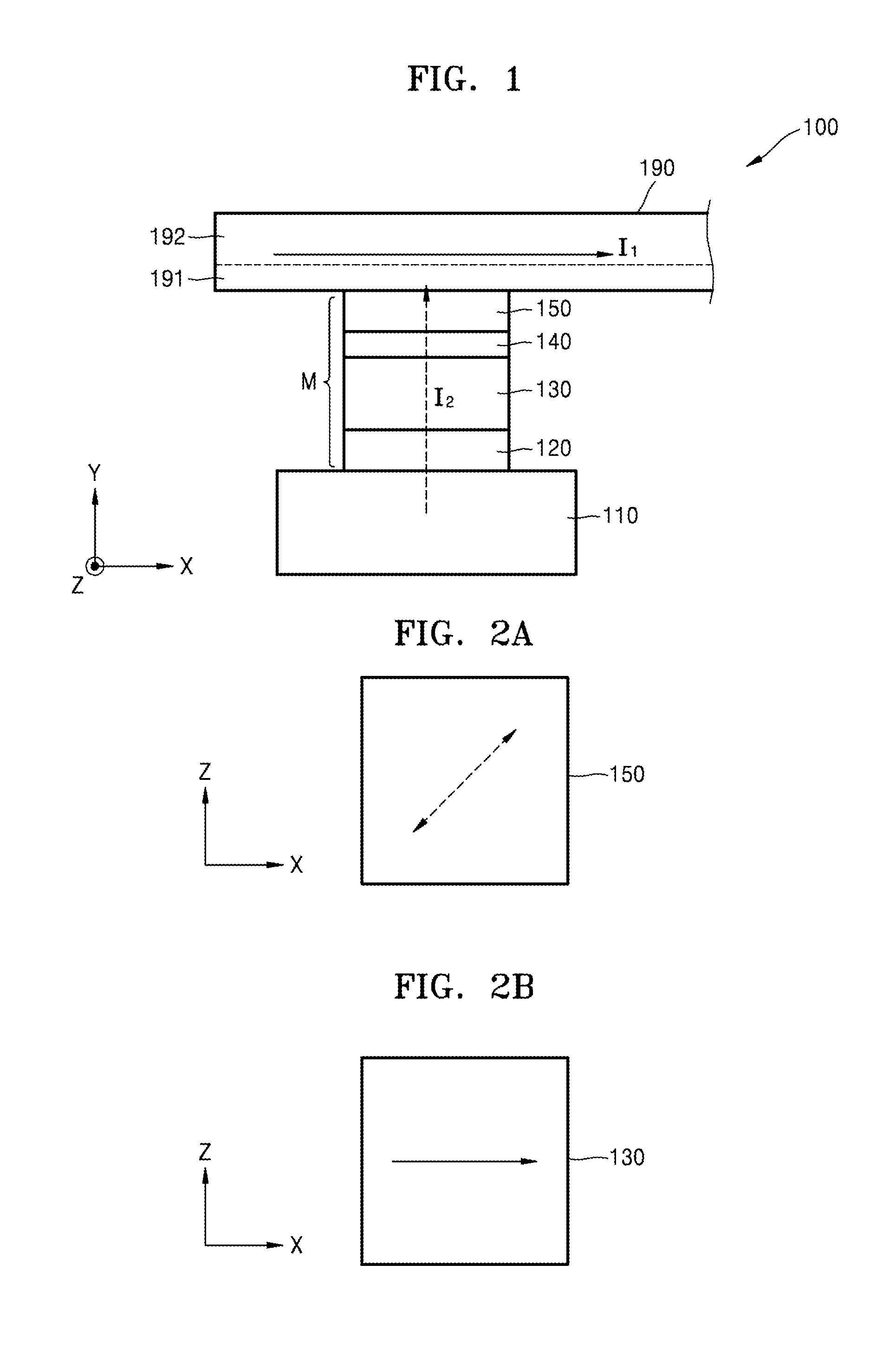
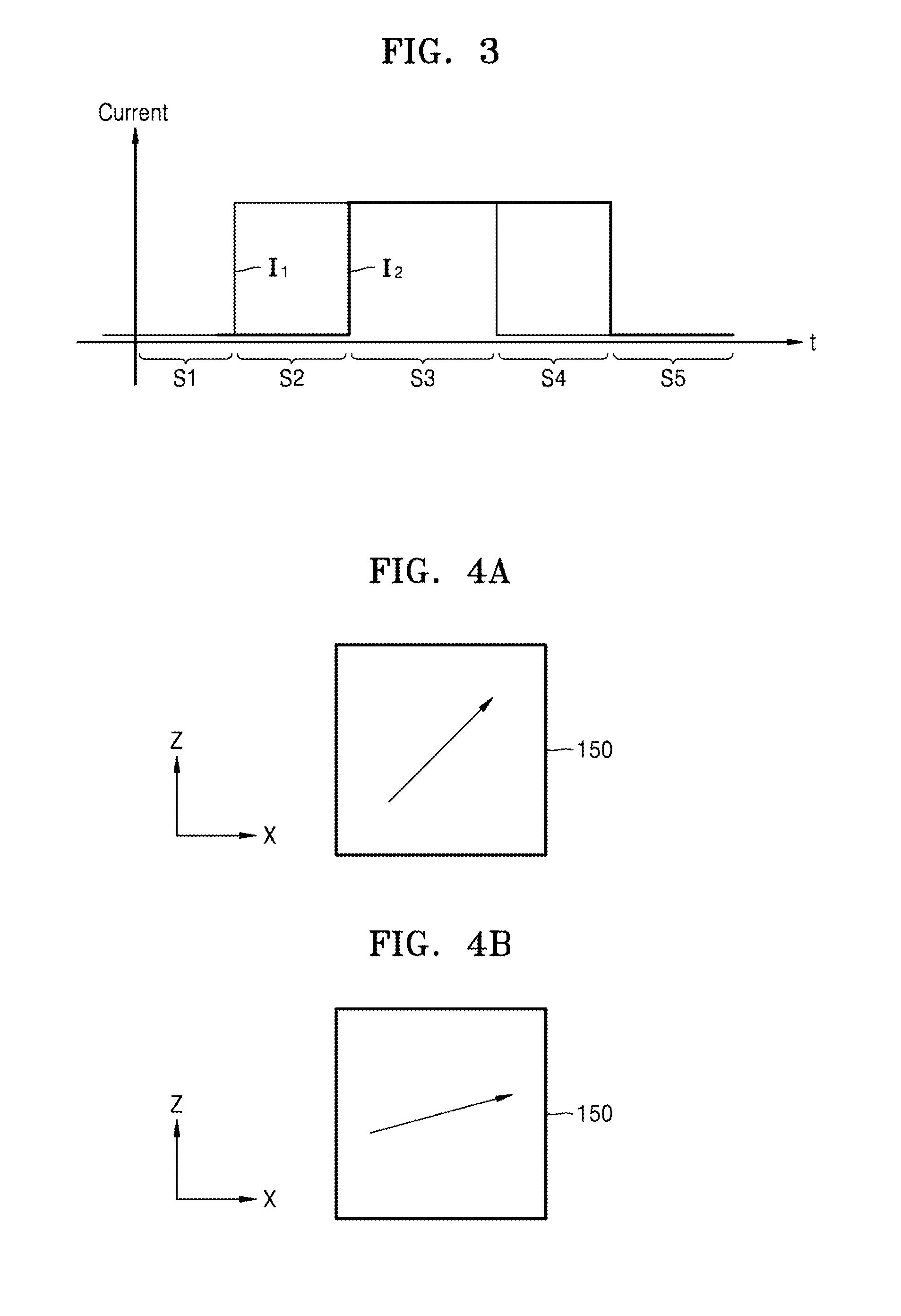
[0045]Various example embodiments will now be described more fully with reference to the accompanying drawings in which some example embodiments are shown. However, specific structural and functional details disclosed herein are merely representative for purposes of describing example embodiments. Thus, the invention may be embodied in many alternate forms and should not be construed as limited to only example embodiments set forth herein. Therefore, it should be understood that there is no intent to limit example embodiments to the particular forms disclosed, but on the contrary, example embodiments are to cover all modifications, equivalents, and alternatives falling within the scope.

[0046]In the drawings, the thicknesses of layers and regions may be exaggerated for clarity, and like numbers refer to like elements throughout the description of the figures.

[0047]Although the terms first, second, etc. may be used herein to describe various elements, these elements should not be limi...


PUM


Abstract

Magnetic memory devices include a magnetoresistive cell including a free layer having a variable magnetization direction and a pinned layer having a fixed magnetization direction, a bit line on the magnetoresistive cell and including a spin Hall effect material layer exhibiting a spin Hall effect and contacting the free layer; and a lower electrode under the magnetoresistive cell. A voltage is applied between the bit line and the lower electrode so that current passes through the magnetoresistive cell.

Description

CROSS-REFERENCE TO RELATED APPLICATIONS[0001]This application claims the benefit of priority under 35 U.S.C. §119 from Korean Patent Application No. 10-2013-0028240, filed on Mar. 15, 2013, in the Korean Intellectual Property Office, the disclosure of which is incorporated herein by reference in its entirety.BACKGROUND[0002]1. Field[0003]Example embodiments relate to magnetic memory devices and / or methods of writing data to the magnetic memory devices.[0004]2. Description of the Related Art[0005]A magnetic random access memory (MRAM) is a memory device that stores information by using a change in resistance of a magnetic tunneling junction (MTJ) element. The resistance of the MTJ varies depending on a magnetization direction of a free layer. When the magnetization direction in the free layer is the same as that of a pinned layer, the MTJ element has a low resistance value. Conversely, when the magnetization direction of the free layer is opposite to that of the pinned layer, the MTJ...

Claims


Application Information

Patent Timeline
IPC IPC(8): G11C11/16
CPCG11C11/1675G11C11/18G11C11/161G11C11/16H10B61/00H10N50/01H10N50/10
Inventor PI, UNG-HWANKIM, KWANG-SEOKKIM, KEE-WONLEE, SUNG-CHULJANG, YOUNG-MAN
Owner SAMSUNG ELECTRONICS CO LTD
Learn More