Portable fundus camera

a camera and camera body technology, applied in the field of vision loss, can solve the problems of vision loss, visual loss, eye disease, etc., and achieve the effects of reducing blindness rates, convenient portability, and improving vision

Inactive Publication Date: 2014-09-18
LUMETRICS
View PDF3 Cites 42 Cited by
  • Summary
  • Abstract
  • Description
  • Claims
  • Application Information

AI Technical Summary

Benefits of technology

[0015]The present invention meets this need by providing a compact portable fundus camera device. The camera can be used by individuals of varying backgrounds. For example, a retina specialist might utilize one such device in each exam lane to speed patient flow; optometrists or general ophthalmologists might find the device economically most favorable as the only mode of photographic documentation of the fundus in their practices; and a primary care provider might use it to document and follow childhood diabetics and patients with other conditions that affect the eyes. The camera enables a user to obtain one or more digital images of the fundus of a patient, deliver such images electronically to an expert reader of such images, and consult with the expert for advice as needed. Health aides, technicians, or nurses may be trained to use the camera to obtain retinal photographs of under-served populations.
[0016]In these settings, the images may be stored and digitally transmitted to qualified image readers to determine the need for further patient observation and / or referral to other medical specialists. The camera is compatible with mobile computing and image viewing platforms (such as tablet PCs, smartphones, hybrid notebooks, etc.) and can be easily integrated into the growing and dynamic field of remote health monitoring. In so doing, the camera can play an important role in helping improve the quality of medical outreach programs as well as reduce rates of blindness and visual disability worldwide.
[0017]Additionally, the camera particularly benefits a growing segment of our populace, the aging population. The instant camera device has utility for population-based screening for potentially blinding retinal and optic nerve diseases, with the potential for significant health and direct and indirect medical cost savings in the geriatric population.
[0019]In certain embodiments, the weight distribution of the camera allows for balanced positioning of the camera housing onto a hand. The user holds the camera similar to how a person holds a pencil. The weight distribution allows the camera to rest on the first dorsal interroseus muscle without the need to hold it with any fingers.

Problems solved by technology

Vision loss is an often feared untoward health event associated with serious medical, psychological, social, and financial consequences.
Vision loss may be caused by many factors, stemming from damage to all parts of the visual system.
Retinal and optic nerve problems have emerged as leading causes of visual loss in developed countries.
These posterior segment ophthalmic conditions are major and growing causes of vision loss globally, as well.
Indirect ophthalmoscopy (at the slit lamp or with a headset) is challenging and generally only performed by ophthalmologists and optometrists.
This device is inexpensive and widely available; however the large magnification and very small field of view combined with the fleeting nature of the images limits the value of direct ophthalmoscopes.
Physicians routinely use direct ophthalmoscopes for rudimentary fundus examinations during patient visits, but such examinations rarely lead to meaningfully diagnosis, follow up conclusions, or referral unless the damage is quite advanced.
Even the emerging smartphone-based imaging technology has not changed the utility of direct ophthalmoscopy.
Bulky, expensive table-top fundus cameras are typically used to acquire high quality true-color and angiographic images of the retina with large fields of view.
The operation of these table-top cameras is very elaborate, and requires a highly trained technician.
These cameras, while having a smaller form-factor than the table-top devices, still lack the simplicity and portability of a device amenable to widespread distribution.
The hand-held units in these cameras are bulky and are attached to a base-station via a thick cable.
Alignment and focusing of the cameras is not intuitive, and in some versions the size of the field of view is inadequate.
In addition, these cameras do not provide a significant reduction in cost, while lacking the imaging quality of the table-top cameras.
Not all patients who could benefit from retinal fundus photography have access to it, even if they have a primary eye care provider.
Likewise, those patients that rely on general practitioners, family practice physicians, internists, and pediatricians for ophthalmic health concerns have essentially no access to comprehensive retinal imaging.
Moreover, special populations, including residents of nursing homes, assisted living facilities or group homes, prisoners, remote populations such as Native Americans on reservations and people residing in very rural communities have restricted access to a comprehensive and well documented fundus evaluation, and fundus imaging.
The problem is even more severe in developing nations, and also in many Western countries where expensive heath care technology is more controlled, such as by government mandate.
Existing fundus cameras are expensive (e.g., $20,000 to $45,000 or more), require considerable technical expertise to operate, and are not easily portable.
As a result, fundus photography as a screening tool has been implemented only to a very limited extent.
The widespread implementation of fundus photography and usage in remote areas has so far not been practical.

Method used


Image

  • Portable fundus camera
  • Portable fundus camera
  • Portable fundus camera

Examples


Embodiment Construction

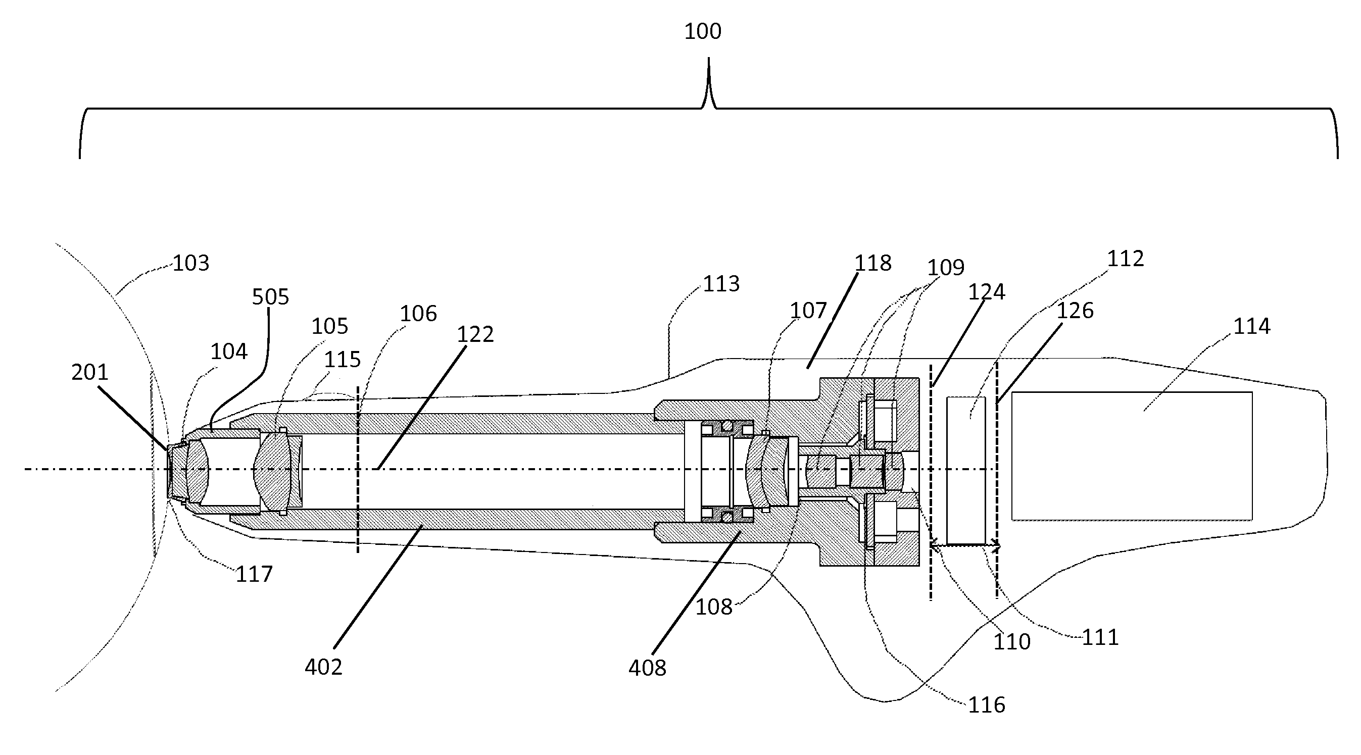
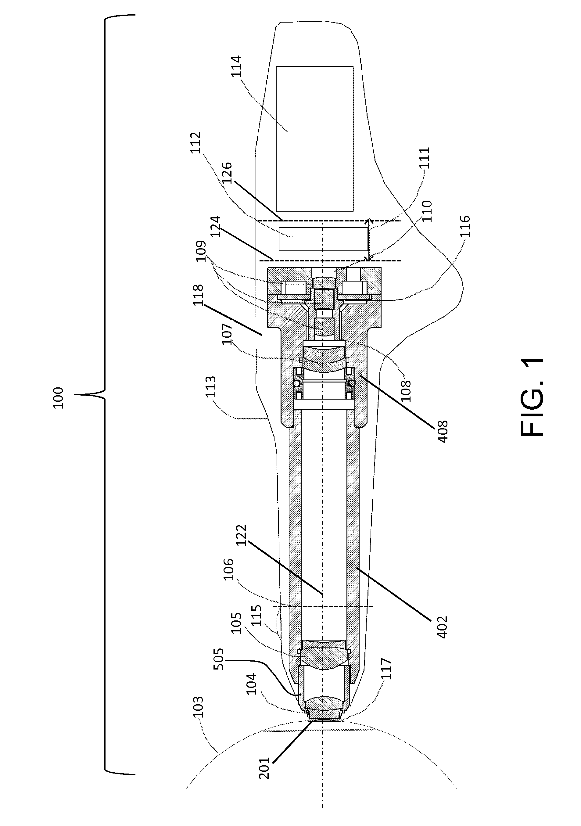
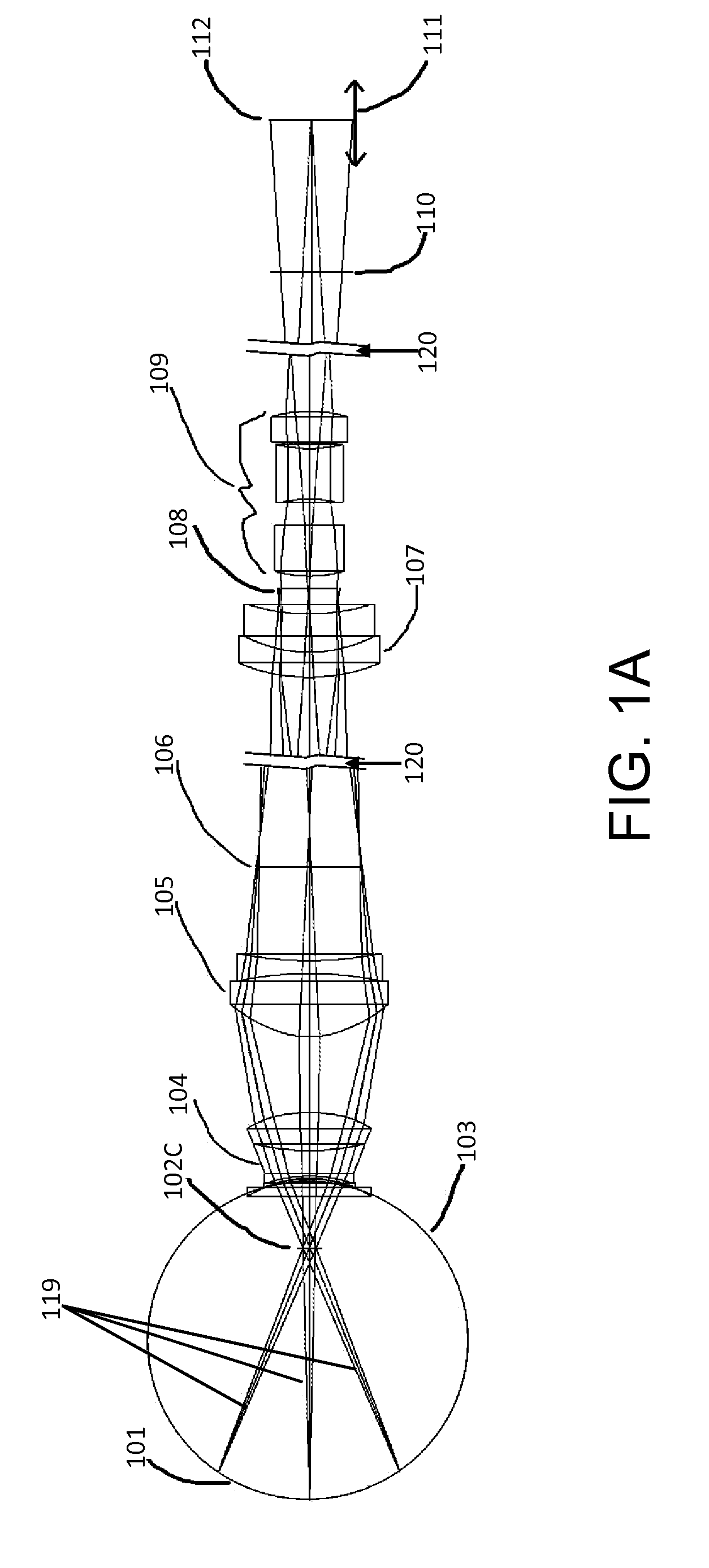
[0043]The present description is directed in particular to elements forming part of, or cooperating more directly with, apparatus, systems and methods in accordance with the invention. For a general understanding of the present invention, reference is made to the drawings. It is to be understood that elements not specifically shown or described may take various forms well known to those skilled in the art. Figures shown and described herein are provided in order to illustrate key principles of operation of the present invention and are not drawn with intent to show actual size or scale. Some exaggeration, i.e., variation in size or scale may be necessary in order to emphasize relative spatial relationships or principles of operation.

[0044]In the drawings, like reference numerals have been used throughout to designate identical elements. The description provided herein may identify certain components with adjectives such as “top,”“upper,”“bottom,”“lower,”“left,”“right,” etc. These ad...


PUM


Abstract

A portable hand-held ocular fundus camera system for imaging the fundus of the eye is disclosed. The camera system is comprised of a camera housing, one or more groups of lens in an internal cavity of the housing, a front group of lenses at the front end of the internal cavity, a contact member to contact at least a portion of the cornea, a light source configured to direct light from locations inside the camera through an annulus near the periphery of the front lens group, so that the light enters the eye through an annulus at the periphery of the pupil of the eye during contact with the cornea. Light from the light source that is reflected off of the fundus that passes through the center portion of the pupil of the eye is imaged onto an imager configured to acquire a sequence of images while an actuator coupled to the imager continuously varies the location of the imager along the optical axis of the camera.

Description

CROSS-REFERENCE TO RELATED APPLICATIONS[0001]This application claims priority from U.S. Provisional Patent Application No. 61 / 789,570 filed Mar. 15, 2013, the disclosure of which is incorporated herein by reference. Reference is also made to commonly-assigned co-pending U.S. patent application Ser. No. 13 / 512,336, which has a 371(c) date of Aug. 1, 2012, and which is a U.S. national stage application of PCT Application No. US2010 / 059000 filed Dec. 4, 2010, and entitled “PORTABLE FUNDUS CAMERA”, by Ignatovich et al., the disclosures of which are incorporated herein by reference.STATEMENT REGARDING FEDERALLY SPONSORED RESEARCH OR DEVELOPMENT[0002]This invention was made with United States Government support. The U.S. Government has a paid-up license in this invention and the right under limited circumstances to require the patent owner to license others on reasonable terms as provided for by the terms of Grant No. 2R44EY020714-02A1 awarded by the National Institutes of Health.BACKGROU...

Claims


Application Information

Patent Timeline
Patent Type & Authority Applications(United States)
IPC IPC(8): H04N5/232H04N5/225
CPCH04N5/2254H04N5/23212A61B3/125A61B3/14
Inventor IGNATOVICH, FILIPP V.GIBSON, DONALD S.MARCUS, MICHAEL A.KLEINMAN, DAVID M.
Owner LUMETRICS
Why Eureka
Try Eureka