
Reinforced flexible pipe

a flexible pipe and reinforcement technology, applied in the direction of flexible pipes, pipe protection, pipe protection, etc., can solve the problems of dredgers' suction and pressure lines that are subject to a considerable amount of wear, and the thick layer of rubber is often destroyed, so as to achieve the effect of faster wear and tear

Inactive Publication Date: 2014-09-11
IHC HOLLAND NV
View PDF11 Cites 9 Cited by
  • Summary
  • Abstract
  • Description
  • Claims
  • Application Information

AI Technical Summary

Benefits of technology

The patent aims to improve the flexibility of a flexible conduit during its lifespan. One way to achieve this is to pretension the layer of the conduit. This improves the effect of the layer when the conduit is pressurized.

Problems solved by technology

A dredge hoses, which is a flexible conduit for transporting abrasive slurry, is inside particularly sensitive to wear when slurry with sharp particles is transported.
Rubber hoses used in suction and pressure lines for dredgers are subject to a considerable amount of wear as the material conveyed there-through cuts the inner wall.
The thick layer of rubber is often destroyed in a short time and the lining of steel inserts is expensive and only effective with suction hoses.
These required spaces to obtain an acceptable flexibility however do result in according unprotected areas of the hose wherein still abrasive particles may penetrate to a certain depth.
However, the thickness of the rings near their inner circumference being smaller does result in an increase of unprotected area of the hose wherein still abrasive particles may penetrate to a certain depth.
In addition, flexibility of the flexible pipe is less controllable during the operational life of the flexible pipe because the amount of rubber between adjacent rings keeps on changing during life of the flexible pipe.
When these known rings break, parts thereof easily break out of the body.
These broken out parts then flow with the slurry and may damage a downstream apparatus.
In addition, the hose will worn out faster without complete wear rings.

Method used


Image

  • Reinforced flexible pipe
  • Reinforced flexible pipe
  • Reinforced flexible pipe

Examples


Embodiment Construction

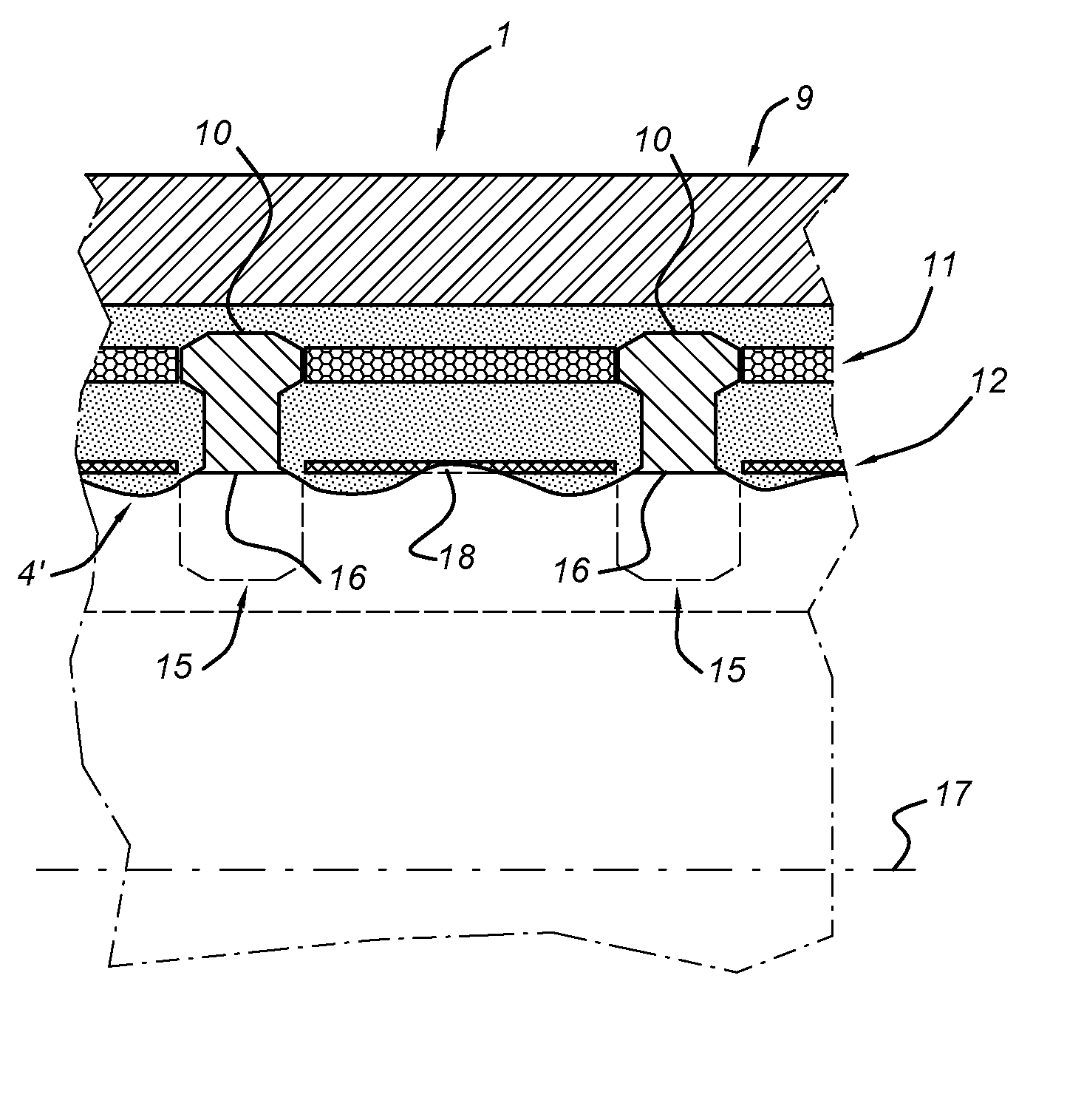
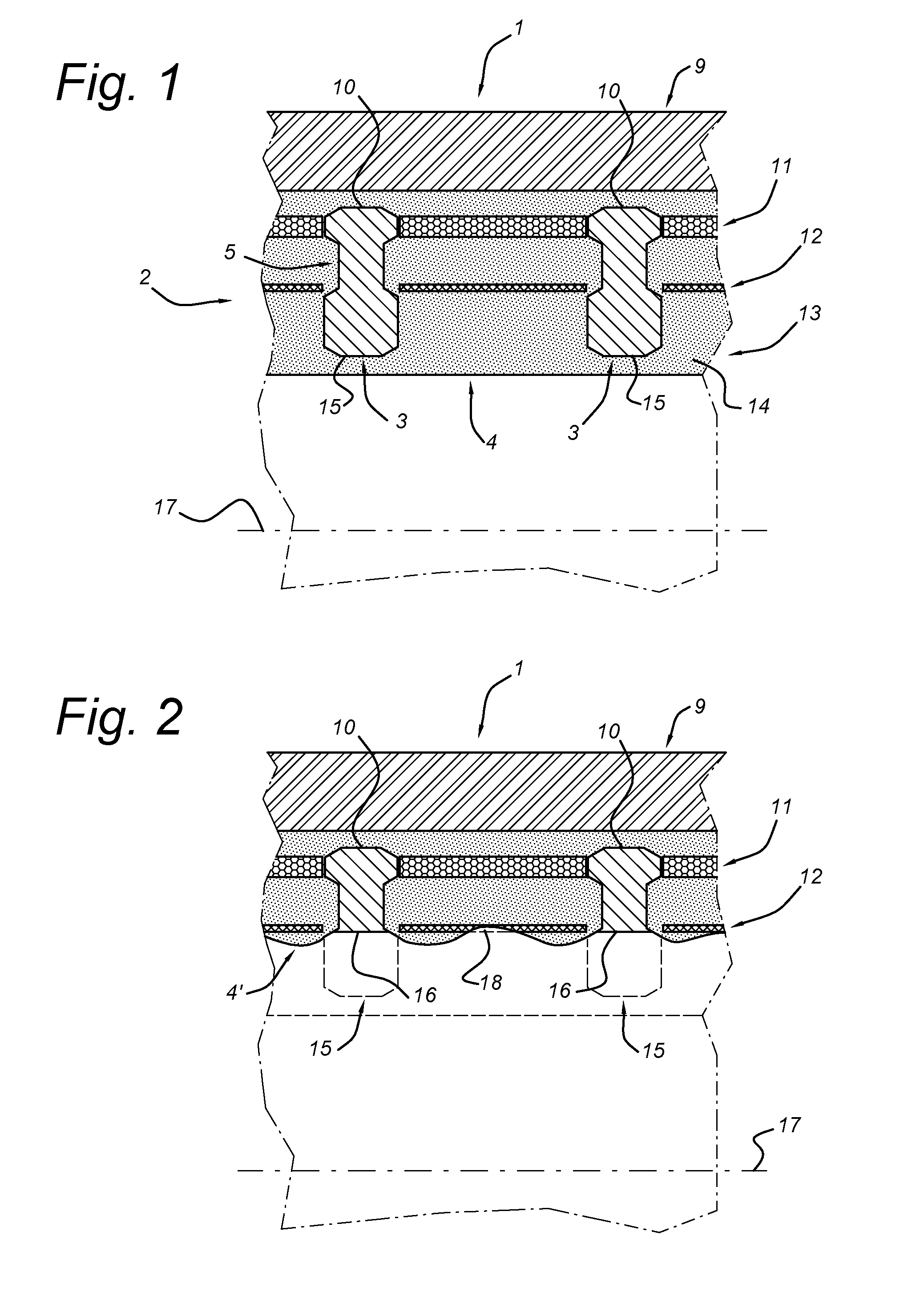
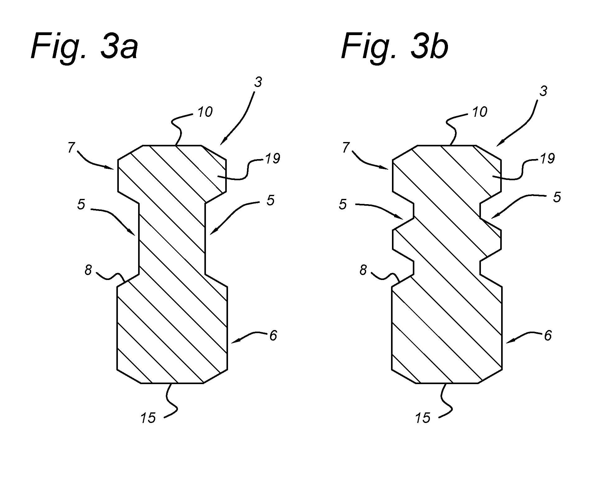
[0035]The invention will be described in detail referring to a preferred embodiment of a flexible conduit 1 shown (or details thereof shown) in the drawings 1-3.

[0036]FIG. 1 depicts a flexible conduit 1 for transporting abrasive slurry. The conduit 1 has a flexible tubular body, in this case a rubber tube 2 however any other suitable flexible polymer or other material is conceivable. A plurality of wear-resistant rings 3 are provided in the body 2 along the length of the conduit 1. The rings 3 are suitable for protecting the inner surface 4 of the body 2 against abrasive action of the slurry. These rings 3 are typically made of steel, however any other conceivable material is conceivable. The rings 3 are co-axial with respect to the longitudinal axis 17 of the conduit 1. A ring 3, specifically several rings 3, more specifically all rings 3 of the plurality of rings 3 comprise an indentation 5 for engaging the tubular body 2 in a form closed manner. Form closed is here to say that th...


PUM


Abstract

A flexible conduit for transporting abrasive slurry, includes a flexible tubular body, such as rubber tube, and a plurality of wear-resistant rings provided in the body along the length of the conduit for protecting the inner surface of the body against abrasive action of the slurry, wherein at least one ring of the plurality of rings includes an indentation for engaging the tubular body in a form closed manner, and wherein the indention is arranged with the ring such that radial movement of the ring with respect to the conduit is prevented.

Description

BACKGROUND[0001]The present invention relates to a flexible conduit for transporting abrasive slurry, comprising a flexible tubular body, such as a rubber tube, and a plurality of wear-resistant rings provided in the body along the length of the conduit for protecting the inner surface of the body against abrasive action of the slurry. This abrasive action may include abrasion, erosion and cutting of sharp edges of pieces of e.g. rock.[0002]U.S. Pat. No. 4,537,224 A relates to a rubber tube for dredging work embedded in and used in a pipe-line used for dredging work in the sea or river. This rubber tube has a tubular body made of rubber having a plurality of strengthening clothes embedded therein, and a plurality of metal rings axially arranged in a suitably spaced relation which are embedded in an inner peripheral surface of said tubular body and which inner peripheral surface forms a part of the inner peripheral surface of said tubular body. The metal rings have their joined surfa...

Claims


Application Information

Patent Timeline
Patent Type & Authority Applications(United States)
IPC IPC(8): F16L11/08F16L11/12
CPCF16L11/12F16L11/08F16L11/081F16L11/085F16L57/06
Inventor GUNSING, THEODORUS WILHELMUS MARIA
Owner IHC HOLLAND NV
Learn More