
Method and device for ascertaining the lateral strip contour or the position of the strip edges of a running metal strip

a technology of running metal strips and contours, which is applied in the direction of measuring devices, mechanical measuring arrangements, instruments, etc., can solve the problems of increasing the complexity of rolling mills, being expensive and maintenance-intensive, etc., and achieves the effects of less wear, improved measurement, and improved service life of wear members

Pending Publication Date: 2021-08-26
PRIMETALS TECH AUSTRIA GMBH
View PDF0 Cites 0 Cited by
  • Summary
  • Abstract
  • Description
  • Claims
  • Application Information

AI Technical Summary

Benefits of technology

The invention provides a construction mode that allows for the efficient use of existing elements in a space-saving manner. The invention also includes a sensing element in the form of a wear member with a wear member adjustment device. The wear member can guide the metal strip and measure path or force, resulting in increased service life and reduced maintenance costs. A plurality of sensing elements can provide better measuring data at multiple locations on the metal strip. Additionally, an apparatus for establishing contact by a preselected starting contact force at the starting time is preferable.

Problems solved by technology

However, the equipment with cameras necessary to this end requires space, increases the complexity of the rolling mill, is expensive and maintenance-intensive, and is prone to errors under the environmental conditions which are unfavorable for optical detection.

Method used


Image

  • Method and device for ascertaining the lateral strip contour or the position of the strip edges of a running metal strip
  • Method and device for ascertaining the lateral strip contour or the position of the strip edges of a running metal strip
  • Method and device for ascertaining the lateral strip contour or the position of the strip edges of a running metal strip

Examples


examples

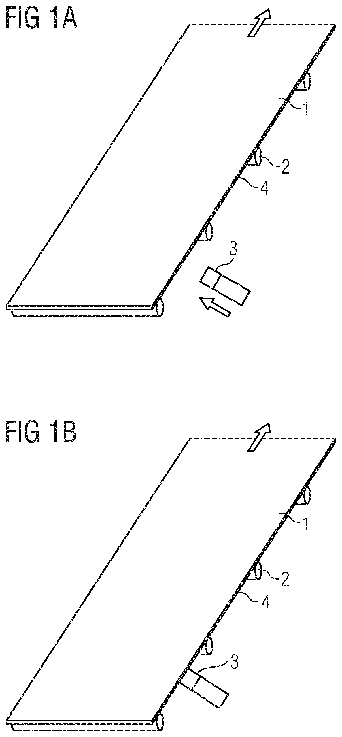
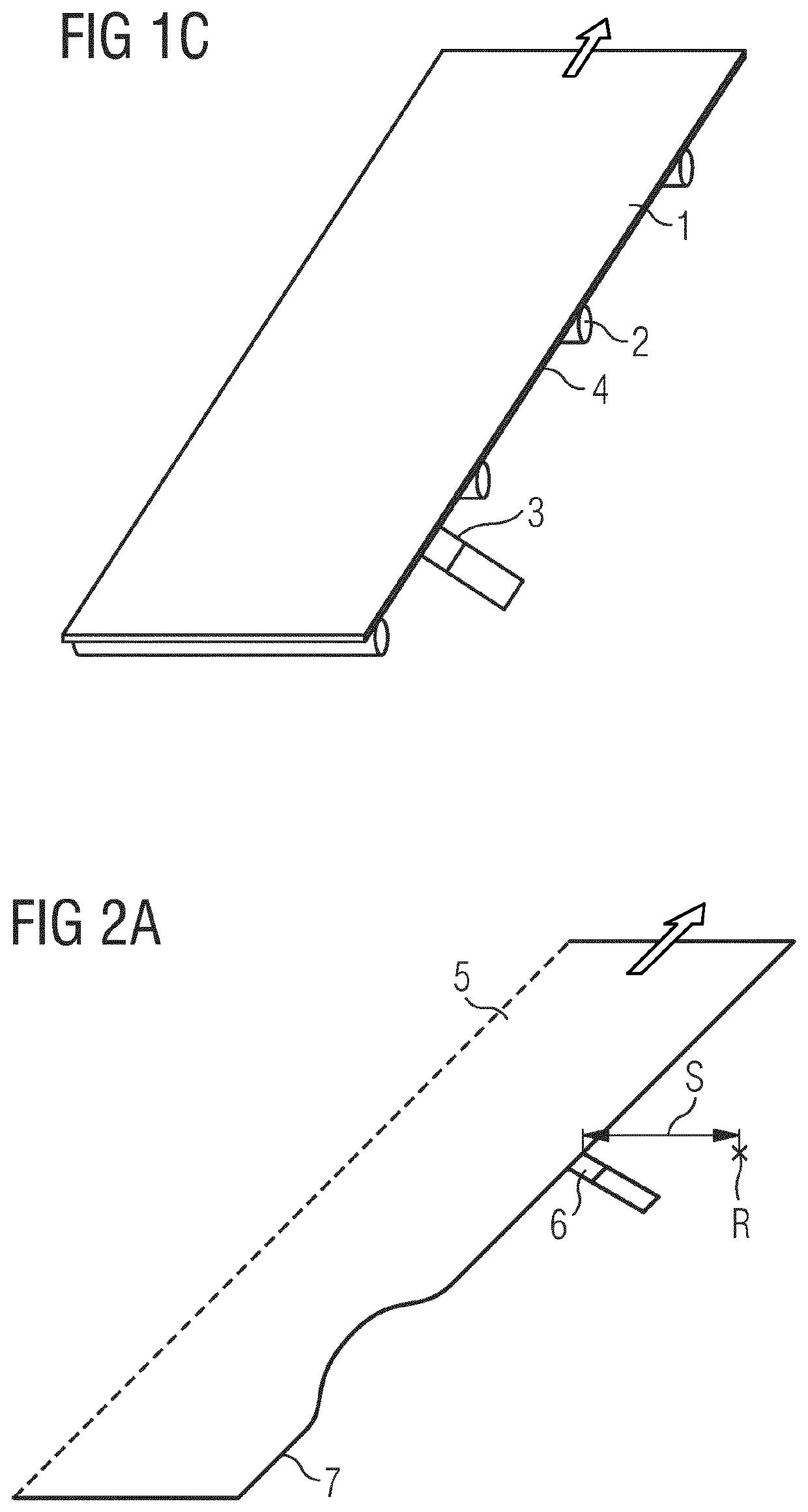
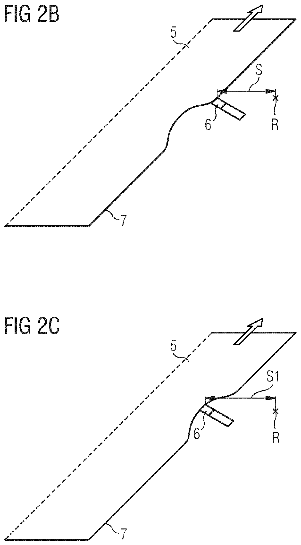
[0056]FIGS. 1a, 1b, 1c schematically show how a method according to the invention for determining the lateral strip contour of a portion of a metal strip running over a metal strip conveyor device of a rolling mill is used.

[0057]It is illustrated in FIG. 1a how a metal strip 1 runs over a metal strip conveyor device, here a roller table having roller table rollers 2. The running direction is indicated by an arrow. A sensing element 3 is present but does not contact the lateral edge 4 of the metal strip 1. It is indicated by a block arrow that the sensing element is moved in the direction of the lateral edge 4.

[0058]The starting time of the method according to the invention is illustrated in FIG. 1b. Contact between the sensing element 3 and the lateral edge 4 has been established. Gathering of measuring data suitable for determining the lateral strip contour and / or the position of the strip edges is commenced, while the portion of the metal strip runs past the sensing element and co...


PUM

PropertyMeasurementUnit
contact forceaaaaaaaaaa
forceaaaaaaaaaa
thicknessaaaaaaaaaa

Abstract

A device for ascertaining the lateral strip contour and / or the position of the strip edges of a metal strip. It includes at least one sensing element for ascertaining suitable measurement data. The sensing element is integrated into a lateral guide (17) together with a main part module of the metal strip conveying device. The lateral guide (17) includes at least one wear element (15a, 15b, 15c) which is arranged in the lateral guide and which comprises a wear element adjusting device that can be rotated about a rotational axis (20) substantially perpendicular to a guide plane of the lateral guide (17). The wear element (15a, 15b, 15c) together with the wear element adjusting device is designed as a sensing element. In an operating method, at least one sensing element (15a, 15b, 15c) is brought into contact with a lateral edge at a starting time, and suitable measurement data is ascertained using the sensing element while the metal strip runs past the sensing element. The strip course can be corrected on the basis of the ascertained measurement data using corrective measures on one or more roll stands and / or on one or more lateral guides (17) of the rolling mill.

Description

CROSS-REFERENCE TO RELATED APPLICATIONS[0001]The present application is a 35 U.S.C. §§ 371 national phase conversion of PCT / EP2019 / 068406, filed Jul. 9, 2019, the contents of which are incorporated herein by reference, which claims priority of European Patent Application No. 18185390.4 filed Jul. 25, 2018, the contents of which are incorporated by reference herein. The PCT International Application was published in the German language.FIELD OF THE INVENTION[0002]The invention relates to a method and to a device for determining the lateral strip contour and / or the position of the strip edges of a metal strip running over a metal strip conveyor device of a rolling mill, and to a method for correcting the running of the strip.PRIOR ART[0003]When rolling metal strips in a rolling mill, the thickness of the metal strips running through roll stands is gradually reduced, wherein the reduction in thickness also leads to variation in the width. The orientation of the lateral edges, also refe...

Claims


Application Information

Patent Timeline
Patent Type & Authority Applications(United States)
IPC IPC(8): B21B39/02B21B1/22
CPCB21B39/02B21B1/22B21B37/22B21B37/68B21B38/00B21B38/04B21B39/14B21B2263/30B21B2273/04G01B5/20G01B5/0009
Inventor MOSER, FRIEDRICH
Owner PRIMETALS TECH AUSTRIA GMBH
Learn More