
Process for removing contaminants from polymeric powders

a technology of polymeric powder and contaminants, applied in the direction of packaging goods type, liquid handling, bundling machine details, etc., can solve the problems of high cost of parts rejected as scrap, additional manufacturing process visual inspection steps, and inability to detect, sort and remove., so as to avoid shadowing, improve detection accuracy, and facilitate contaminant detection

Inactive Publication Date: 2014-09-11
HOWMEDICA OSTEONICS CORP
View PDF10 Cites 21 Cited by
  • Summary
  • Abstract
  • Description
  • Claims
  • Application Information

AI Technical Summary

Benefits of technology

The present invention involves using a special detection apparatus to detect foreign particles in medical grade powder. The detection is based on color, size, and density with specific detection algorithms. The system can remove the detected foreign particles using a vacuum suction or mechanical sorting system. The process results in clean, contamination-free powder. The invention also includes a calibration method using a mixture of known foreign particles and UHMWPE raw material to ensure the equipment is calibrated for the specific powder. The calibration results in no false positives or shadows, and ensures good raw material is not detected as foreign particles. This improves operating ranges and avoids a decrease in production capacity.

Problems solved by technology

At present no technology is available for detecting, sorting and removing foreign particles from UHMWPE powder since medical device manufacturers procure only the pressed bar stock from a small number of compression molding vendors for medical devices.
Due to the inherent difficulty in inspecting thick bar or rod stock procured from these vendors for embedded foreign particles, medical device manufacturers rely on final visual inspection of a completely machined or molded part to identify and eliminate parts with foreign particles.
This results in a high cost in parts rejected as scrap and also additional manufacturing process visual inspection steps.

Method used


Image

  • Process for removing contaminants from polymeric powders
  • Process for removing contaminants from polymeric powders
  • Process for removing contaminants from polymeric powders

Examples


Embodiment Construction

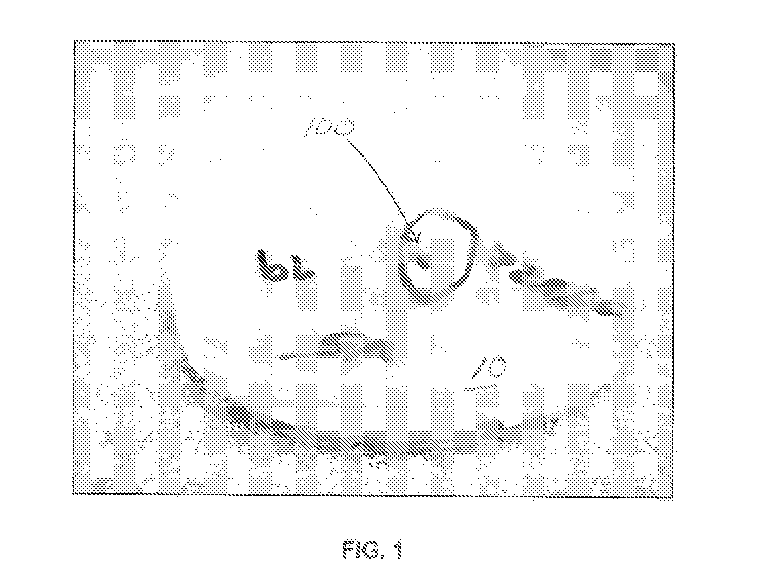
[0034]Referring to FIGS. 1, 3 and 3A, there is shown a series of completed tibial bearing components 10, 12, 14 and 16 manufactured from rod or bar stock made of ultrahigh molecular weight polyethylene (UHMWPE), which have failed a standard inspection test. As can be seen in components 10, 12 and 14, large darkish color contaminants 100 are present in the completely manufactured tibial implants. Because of these contaminants, the manufactured parts had to be scrapped with the obvious entire loss of the cost of the material and manufacturing process. In some cases, manufactured UHMWPE bearings for tibial, patella, glenoid, and acetabular implants had a scrap rate of 5-10% resulting in the loss of thousands of dollars.

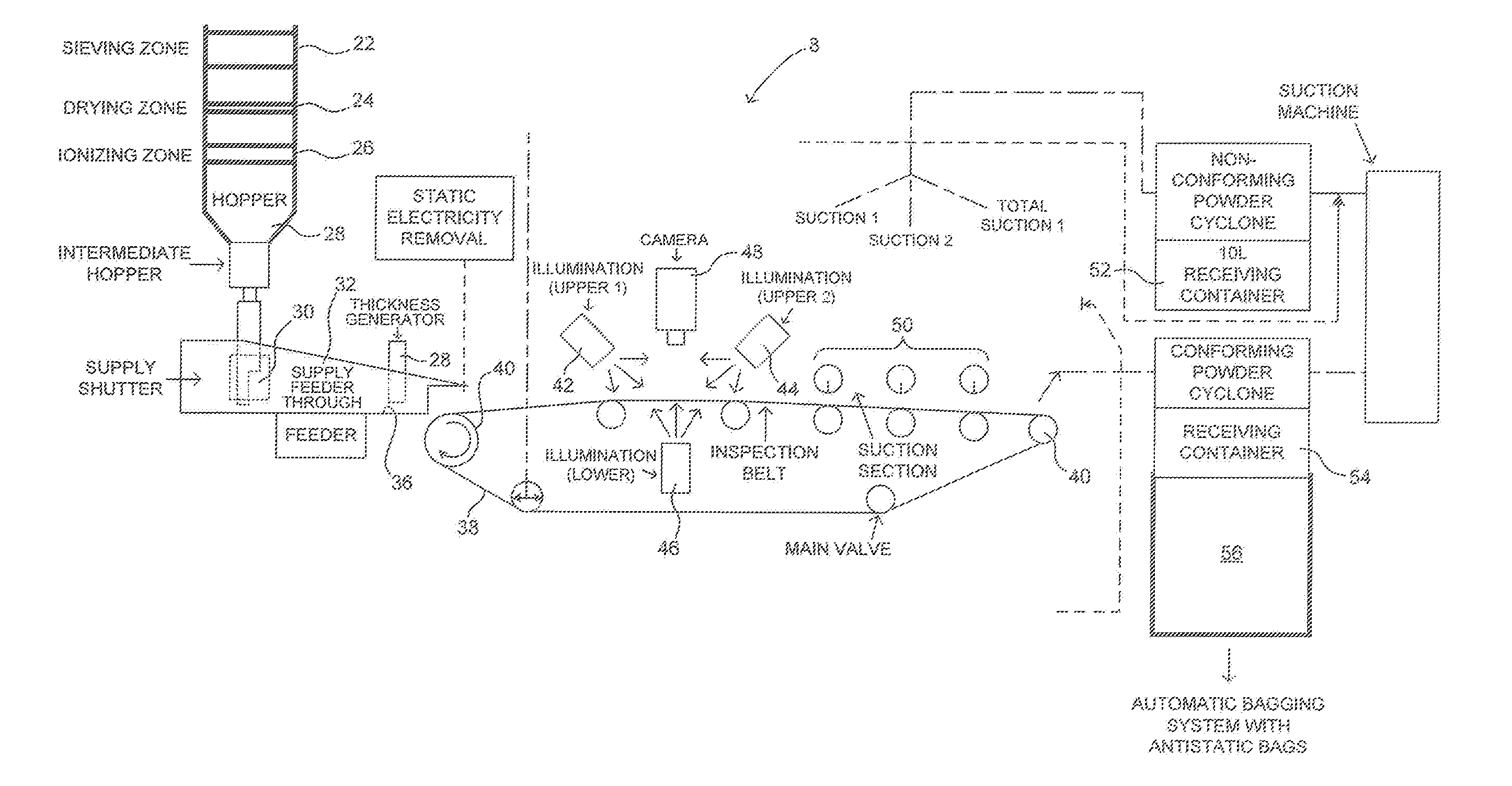
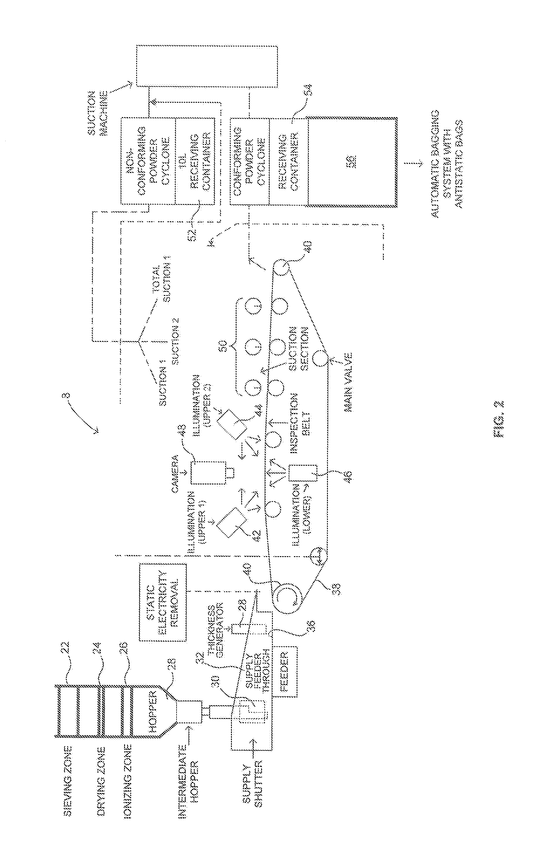
[0035]Referring to FIG. 2, there is shown schematically an apparatus 8 for performing a process for removing contaminants 100 such as that shown in FIGS. 1 and 3. In the process and apparatus described in FIG. 2 raw (untreated) polyethylene powder having a particular siz...


PUM

PropertyMeasurementUnit
heightaaaaaaaaaa
particle sizeaaaaaaaaaa

Abstract

A method for detecting and removing foreign particles in polymeric resin powder comprising drying the resin powder; removing static energy from the resin powder; producing a layer of resin powder 0.2 to 0.8 mm in height in a feeding tray which feeds a conveyor; conveying the layer of resin powder with a transparent conveyor belt at a speed of between 12.2 and 36.64 meters / minute into a foreign particle detection zone; illuminating the polymeric resin powder in the detection zone from above and below with a light; continuously imaging the resin powder from above with a high speed digital CCD camera; continuously analyzing the images with a control device to detect particles having nonwhite colors; and actuating a suction system with the controller to suction off any detected particles to produce a polymeric resin powder having a reduced number of foreign particles.

Description

BACKGROUND OF THE INVENTION[0001]Ultrahigh molecular weight polyethylene (UHMWPE) medical grade plastic material is used in the manufacture of orthopedic bearing surfaces such as for the tibia, patella, glenoid, and acetabular shells. UHMWPE has superior wear resistant properties. The polymer raw material is in the form of a powder and is usually compression molded into bar or rod stock and implant bearing elements are machined from the bar stock to final end product by the implant manufacturer. Alternatively, the implant bearing components can be directly compression molded from the powdered material.[0002]For superior bearing surface applications it is essential that the bearing surface is free of contaminations and imperfections. The final machined bearing component parts are subjected to visual inspection for embedded foreign particles (contaminations / inclusions) as shown in FIG. 1 and if detected in the final part the entire machined part is rejected as scrap. This results in c...

Claims


Application Information

Patent Timeline
Patent Type & Authority Applications(United States)
IPC IPC(8): C08F110/02B65B1/00
CPCB65B1/00C08F110/02B07C5/3422
Inventor PRABHU, BALAJIMASCLES, JEROME
Owner HOWMEDICA OSTEONICS CORP
Learn More