
Vehicle Air Conditioning Apparatus

a vehicle air conditioning and apparatus technology, applied in the field of vehicle air conditioning apparatus, can solve the problems of difficulty in acquiring exhaust heat that can heat the air by using electric motors without engines, and the above-mentioned vehicle air conditioning apparatus is not applicable to electric cars, so as to increase the quantity of heat released in the radiator, increase the condensing pressure of the refrigerant, and secure the effect of heating

Active Publication Date: 2014-09-04
SANDEN CORP
View PDF16 Cites 7 Cited by
  • Summary
  • Abstract
  • Description
  • Claims
  • Application Information

AI Technical Summary

Benefits of technology

The present invention is a vehicle air conditioning system that can always provide air to the vehicle interior at a set temperature. It does this by ensuring that the radiator in the system releases the necessary amount of heat during a cooling and dehumidifying process. By increasing the pressure of the refrigerant in the radiator, the system can always provide the necessary heating for the air that is blown into the vehicle. This technology ensures that the vehicle interior is always comfortable, regardless of external temperatures.

Problems solved by technology

Generally, an electric car uses an electric motor as a power source, and it is difficult to acquire the exhaust heat that can heat the air by using the electric motor without an engine.
Therefore, the above-mentioned vehicle air conditioning apparatus is not applicable to electric cars.

Method used


Image

  • Vehicle Air Conditioning Apparatus
  • Vehicle Air Conditioning Apparatus
  • Vehicle Air Conditioning Apparatus

Examples


Embodiment Construction

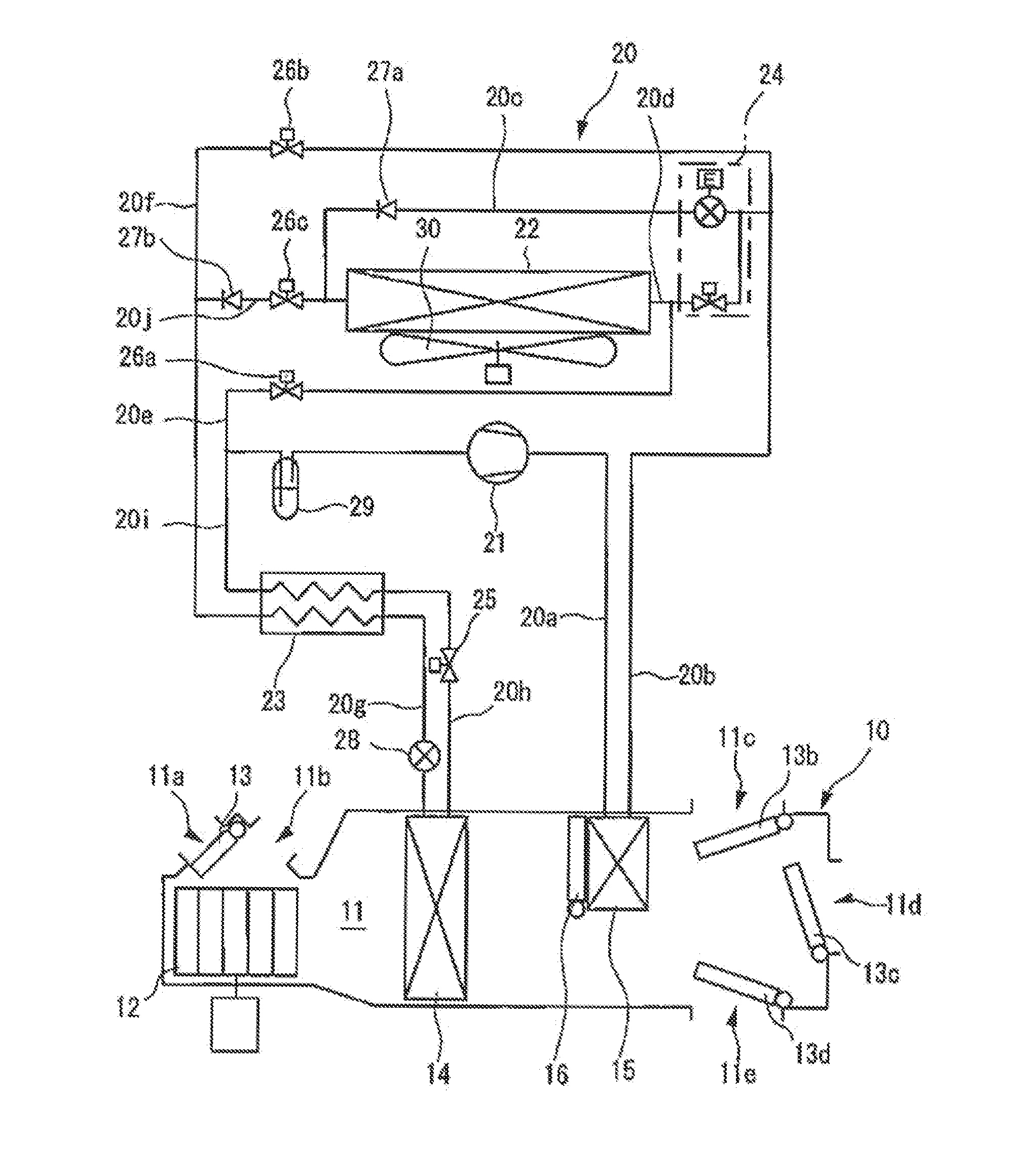
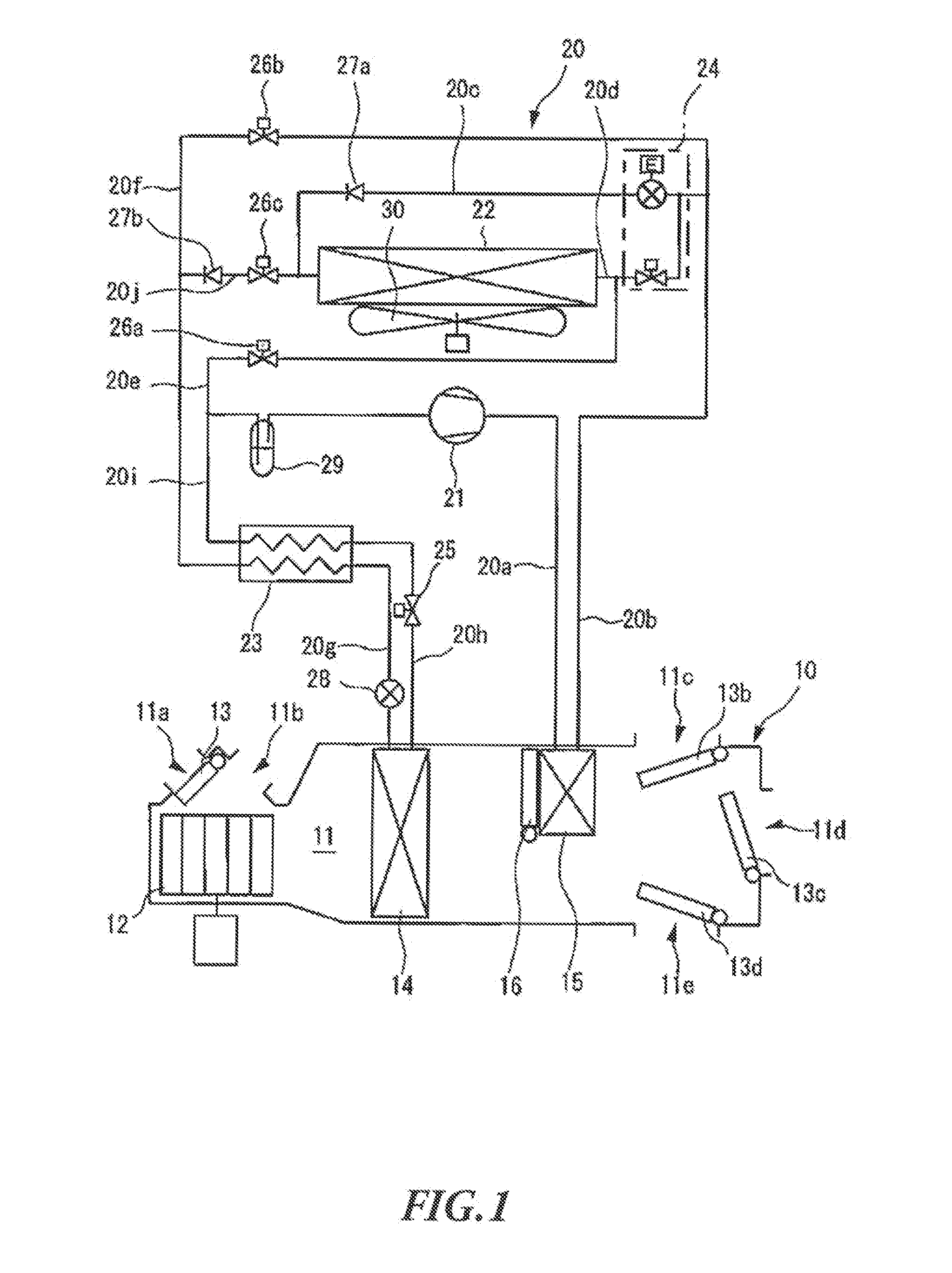
[0020]FIGS. 1 to 8 show an embodiment of the present invention.

[0021]As shown in FIG. 1, the vehicle air conditioning apparatus according to the present invention includes an air conditioning unit 10 provided in the vehicle, and a refrigerant circuit 20 formed across the vehicle interior and the outdoor.

[0022]The air conditioning unit 10 includes an air flow passage 11 that allows the air to foe supplied to the vehicle interior to flow through. An outdoor air inlet 11a and an indoor air inlet 11b are provided in the first end side of the air flow passage 11. The outdoor air inlet 11a is configured to allow the outdoor air to flow into the air flow passage 11, and the indoor air inlet 11b is configured to allow the indoor air to flow into the air flow passage 11. Meanwhile, a foot outlet 11c, event outlet 11d and a defroster outlet 11e are provided in the second end side of the air flow passage 11. The foot outlet 11e is configured to allow the air flowing through, the air flow passa...


PUM


Abstract

A vehicle air conditioning apparatus can ensure that the temperature of the air supplied to the vehicle interior is a preset temperature by securing the quantity of heat release for the radiator during a cooling and dehumidifying operation. The valve opening of the condensing pressure regulating part of the first control valve is smaller when the calculated opening SW of the air mix damper is equal to or more than the predetermined value than when the opening SW is smaller than the predetermined value. Accordingly, when the quantity of heat release is not sufficient in the radiator, it is possible to increase the condensing pressure of the refrigerant in the radiator to raise the temperature of the refrigerant in the radiator. Consequently, it is possible to secure the amount of heating, and therefore to ensure that the temperature of the air supplies to the vehicle interior is a preset temperature.

Description

TECHNICAL FIELD[0001]The present invention relates to a vehicle air conditioning apparatus applicable to, for example, electric cars.BACKGROUND ART[0002]Conventionally, this sort of vehicle air conditioning apparatus includes: a compressor driven by an engine as a power source of a vehicle; a radiator provided outside the vehicle; and a heat exchanger provided inside the vehicle interior. With this vehicle air conditioning apparatus, a cooling operation is performed by: releasing the heat from the refrigerant discharged from she compressor in the radiator; absorbing the heat into the refrigerant in the heat exchanger; and supplying the air subjected to a heat exchange with the refrigerant in the heat exchanger to the vehicle interior. In addition, such a conventional vehicle air conditioning apparatus includes a heater core and perform a heating operation by: releasing the exhaust heat from the cooling water used to cool the engine in the heater core; and blowing the air subjected t...

Claims


Application Information

Patent Timeline
Patent Type & Authority Applications(United States)
IPC IPC(8): B60H1/00
CPCB60H1/00021B60H1/00785B60H1/00835B60H1/00885F25B6/04F25B40/00F25B2313/0293F25B2313/0294F25B2400/0403F25B2400/0409F25B2400/0411F25B2400/0417F25B2400/0419F25B2600/111F25B2600/112F25B2700/1931F25B2700/1933F25B2700/2104F25B2700/2106F25B2700/21151F25B2700/21152F25B2700/2117F25B2700/21171
Inventor MIYAKOSHI, RYOSUZUKI, KENICHI
Owner SANDEN CORP
Learn More