
Imaging system

a technology of imaging system and document reading unit, which is applied in the field of imaging system, can solve the problems of inability to maintain the productivity (reading speed) of the document reading unit, the document reading unit does not particularly take the transmission speed between the document reading unit and the imaging unit into account, and achieves the effect of increasing the reading speed of the ad

Active Publication Date: 2014-08-28
RISO KAGAKU CORP
View PDF2 Cites 0 Cited by
  • Summary
  • Abstract
  • Description
  • Claims
  • Application Information

AI Technical Summary

Benefits of technology

The patent text describes an imaging system that prevents processing speed from being affected by data transfer operations. The system analyzes the amount of data before and after processing, and if the amount of data before processing is smaller, the system outputs the data before processing. This allows for efficient output of image data from the system without reducing productivity. The system also allocates processing operations to either the output-side processing section or the imaging-side processing section based on the amount of data to be transferred per unit time and the transferable amount of data transmission per unit time, ensuring efficient processing without exceeding the output-side processing section's capacity. The technical effects of this imaging system include better processing speed and higher productivity.

Problems solved by technology

In such a case, the transmission speed becomes a bottleneck to data transfer and the productivity (reading speed) of the document reading unit may not be maintained.
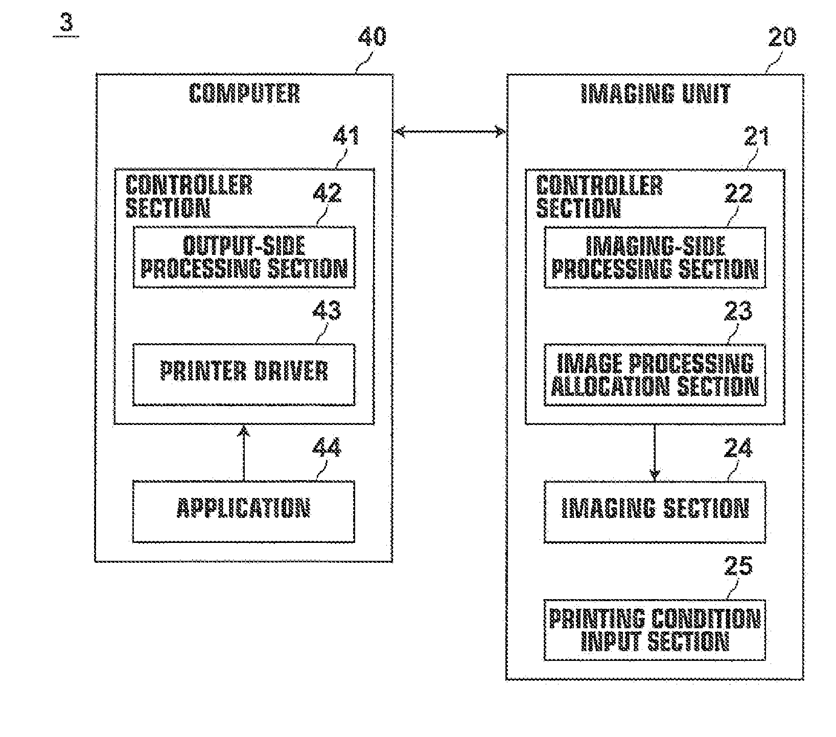
This problem is not limited to the case where image data is transferred from the document reading unit to the imaging unit, but may also arise in a case where image data is transferred from a computer to the imaging unit.
Patent Document 1, however, does not particularly take the transmission speed between the document reading unit and the imaging unit into account.
Thus, the method of Patent Document 1 is not an efficient method.

Method used


Image

  • Imaging system
  • Imaging system
  • Imaging system

Examples


first embodiment

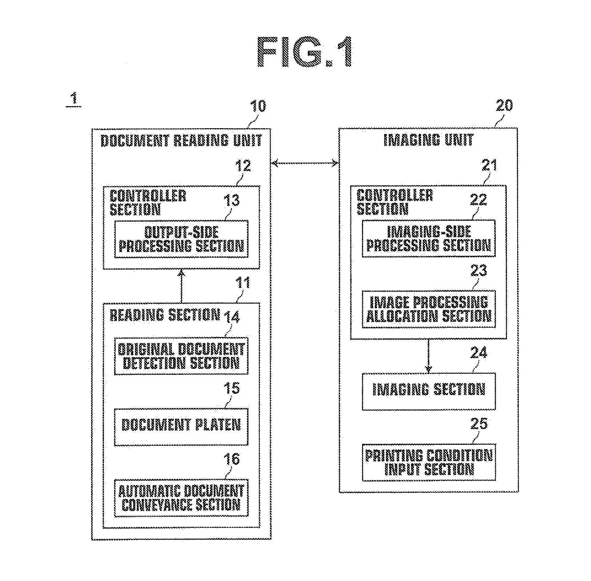
[0027]Hereinafter, a printer system employing an imaging system of the present invention will be described in detail with reference to the drawings. FIG. 1 is a block diagram illustrating the schematic configuration of a printer system 1 of this embodiment.

[0028]As shown in FIG. 1, the printer system 1 of this embodiment includes a document reading unit 10 (which corresponds to an image data output unit of this embodiment), and an imaging unit 20. The document reading unit 10 and the imaging unit 20 are connected to each other via a wired or wireless connection, such as a USB (Universal Serial Bus) cable, a network cable, or a wireless communication line, such as a wireless LAN (Local Area Network).

[0029]The document reading unit 10 includes: a reading section 11 for photoelectrically reading an original document and outputting an image signal; and a controller section 12 for controlling the reading section 11 and performing predetermined processing operations on the image signal ou...

case 1

[0059 is a case where printing conditions specifying the PRINT mode, a scaling factor of 100% (no magnification) and color printing are set and inputted, and one sheet of A4-size original document is placed on the document platen 15 or the automatic document conveyance section 16 of the reading section 11.

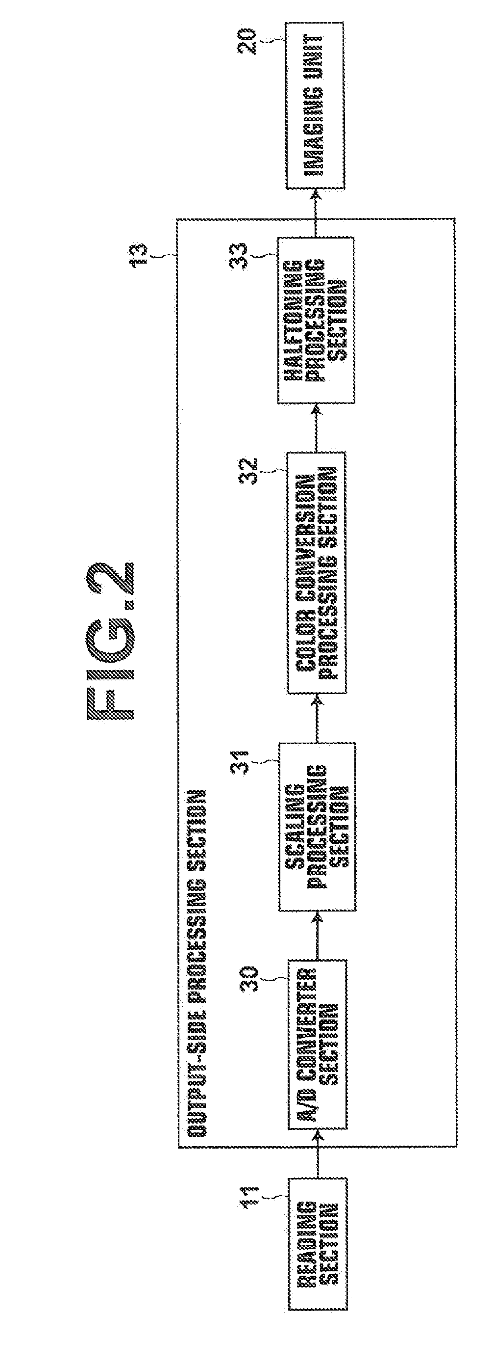
[0060]In the case 1, the information outputted from the original document detection section 14 indicates one sheet of A4-size original document. Therefore, based on this information, the image processing allocation section 23 calculates the maximum amount of data of a sheet of A4-size original document, which is 24.9 MB, and calculates the amount of data of processed image data after the scaling, which is 24.9 MB since the scaling factor is 100% (no magnification). With respect to the color conversion, the amount of data of processed image data is calculated based on the information specifying color printing. Specifically, the RGB image data is converted into to CMYK image data, an...

case 2

[0061 is a case where printing conditions specifying the PRINT mode, a scaling factor of 141% (enlargement) and color printing are set and inputted, and one sheet of A4-size original document is placed on the document platen 15 or the automatic document conveyance section 16 of the reading section 11.

[0062]In the case 2, similarly to the case 1, the information outputted from the original document detection section 14 indicates one sheet of A4-size original document. Therefore, the image processing allocation section 23 calculates the maximum amount of data of a sheet of A4-size original document, which is 24.9 MB, and calculates the amount of data of processed image data after the scaling based on the information of the scaling factor of 141% (enlargement) as follows: 24.9 MB×141%=35.1 MB. With respect to the color conversion, the amount of data of processed image data is calculated based on the information specifying color printing. Specifically, similarly to the case 1, the RGB i...


PUM


Abstract

An image data output unit including an output-side processing section for performing a plurality of processing operations on image data, and an imaging unit including an imaging-side processing section for performing a given processing operation on image data outputted from the image data output unit and an imaging operation section for performing an imaging operation based on the image data outputted from the imaging-side processing section are provided. An amount of data to be transferred per unit time of processed image data that will result when the processing operations are performed on the image data at the output-side processing section is compared with a transferable amount of data transmission per unit time between the image data output unit and the imaging unit, and each of the processing operations is allocated to the output-side processing section or the imaging-side processing section based on the result of the comparison.

Description

BACKGROUND OF THE INVENTION[0001]1. Field of the Invention[0002]The present invention relates to an imaging system that includes an image data output unit for performing a plurality of processing operations to image data and outputting the processed image data, and an imaging unit for performing an imaging operation based on the image data outputted from the image data output unit.[0003]2. Description of the Related Art[0004]Conventionally, various imaging systems that include a document reading unit for photoelectrically reading an original document to generate image data, performing predetermined processing operations on the image data and outputting the processed image data, and an imaging unit for performing an imaging operation based on the image data outputted from the document reading unit are proposed (see, for example, Japanese Unexamined Patent Publication Nos. 2001-277612, 2008-054209, 2002-300353 and H10 (1998)-285323 (hereinafter, Patent Documents 1, 2, 3 and 4, respect...

Claims


Application Information

Patent Timeline
Patent Type & Authority Applications(United States)
IPC IPC(8): H04N1/024
CPCH04N1/02418H04N1/40068
Inventor SHIOKAWA, MITSUHARU
Owner RISO KAGAKU CORP
Learn More