Air conditioning apparatus
a technology for air conditioning and equipment, applied in lighting and heating equipment, refrigeration components, heating types, etc., to achieve the effect of high accuracy and automatic specification of malfunctioning parts in a short tim
- Summary
- Abstract
- Description
- Claims
- Application Information
AI Technical Summary
Benefits of technology
Problems solved by technology
Method used
Image
Examples
embodiment 1
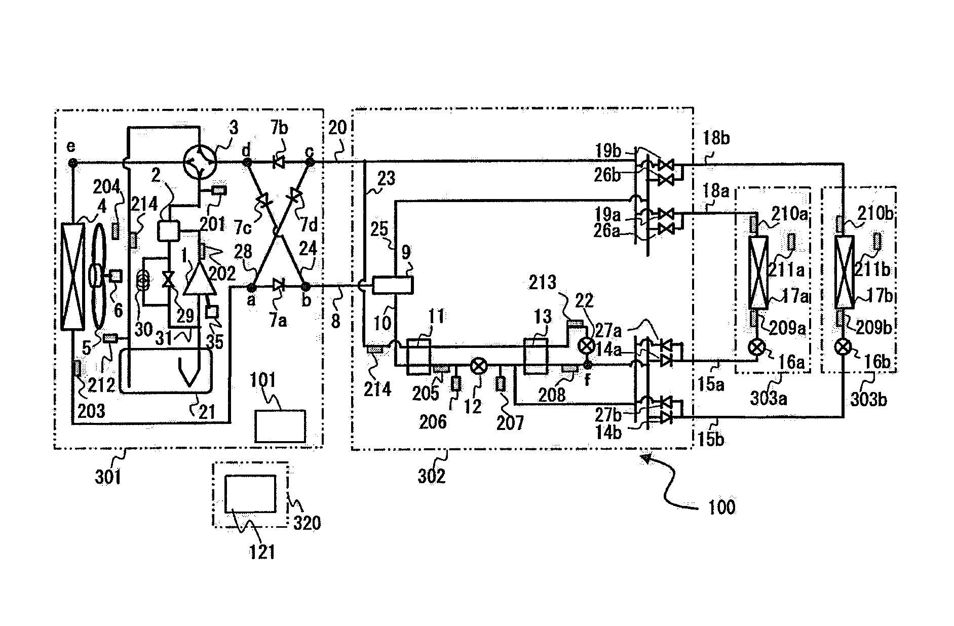
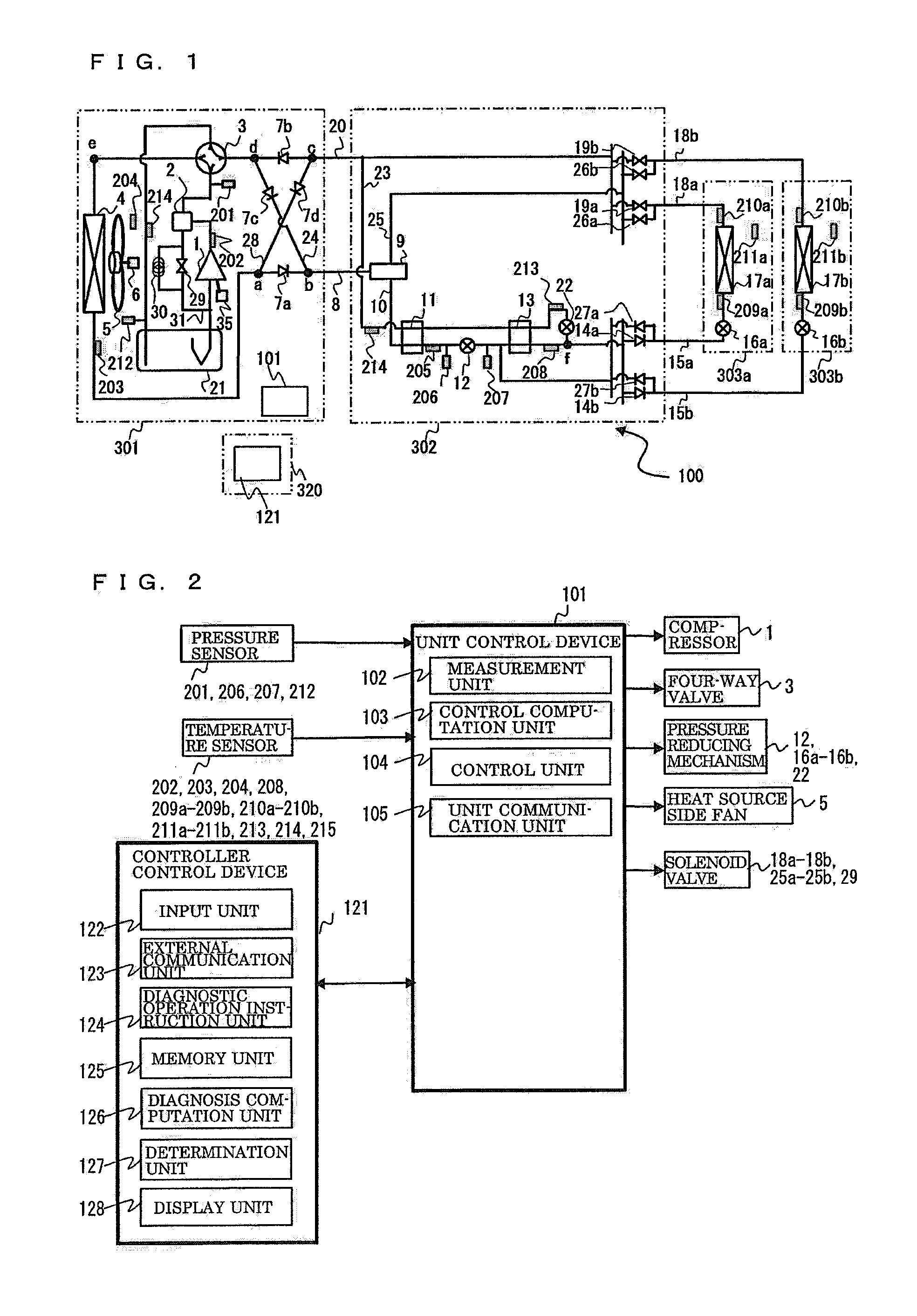
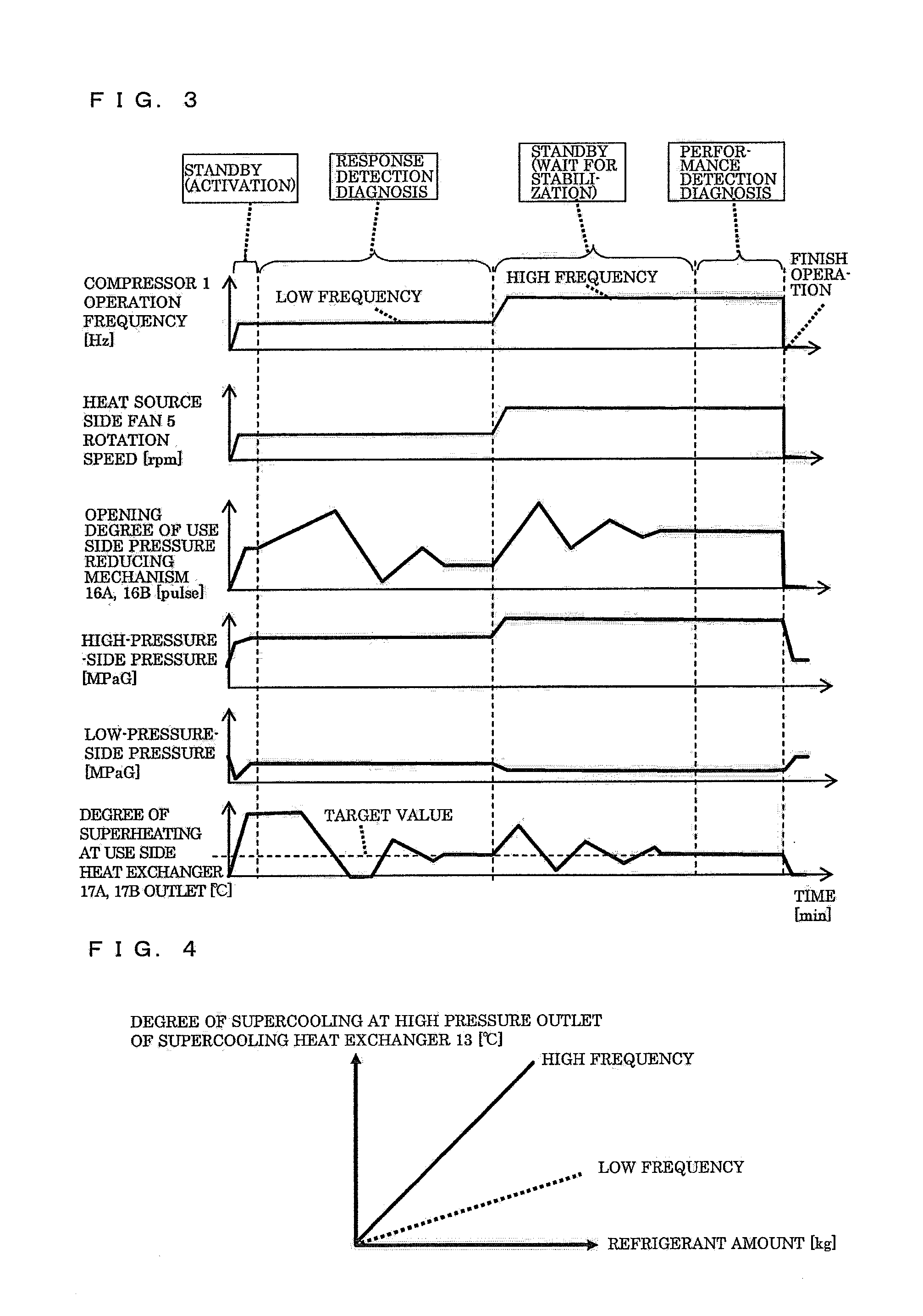
[0023]FIG. 1 is a schematic diagram showing a refrigerant circuit configuration of an air-conditioning apparatus 100 according to Embodiment 1 of the present invention. FIG. 2 is a block diagram showing the configuration of a unit control device 101 and a controller control device 121 of the air-conditioning apparatus 100. Based on FIG. 1 and FIG. 2, the configuration of the air-conditioning apparatus 100 will be described.
[0024]This air-conditioning apparatus 100 is installed on a building or an apartment or a trade establishment, and can perform concurrent operation of cooling and heating by performing refrigeration cycle operation that circulates refrigerant in vapor compression system for air-conditioning to individually process cooling instructions (cooling ON / OFF) or heating instructions (heating ON / OFF) selected at the use units 303a and 303b.
Configuration of Air-Conditioning Apparatus 100
[0025]The air-conditioning apparatus 100 includes a heat source unit 301, a relay unit ...
embodiment 2
[0153]Embodiment 2 describes principally the point of difference from Embodiment 1, and explanations are omitted for those portions which are same as Embodiment 1. The configuration of the air-conditioning apparatus according to Embodiment 2 is the same as the configuration of the air-conditioning apparatus 100 according to Embodiment 1. The portions different from Embodiment 1 are that it executes trouble diagnosis operation in order to determine whether the construction state is appropriate after the installation work of the air-conditioning apparatus.
[0154]In the installation work, the worker connects the heat source unit 301 and the relay unit 302 with a high pressure pipe 8 and a low-pressure pipe 20 on the installation place, and connects the relay unit 302 and the use units 303a, 303b with the indoor liquid branch pipes 15a, 15b and the indoor gas branch pipes 18a, 18b. Thereafter, the branching port to which the indoor liquid branch pipes 15a, 15b and the indoor gas branch p...
embodiment 3
[0164]FIG. 9 is a schematic diagram showing the refrigerant circuit configuration of the air-conditioning apparatus 300 according to Embodiment 3 of the present invention. Based on FIG. 9, the configuration of the air-conditioning apparatus 300 will be described. Embodiment 3 principally describes the point of difference from Embodiment 1 described above, and the explanations for the portions of the same working are omitted with the same signs being adhered.
[0165]The air-conditioning apparatus 300 is different from the air-conditioning apparatus 100 according to Embodiment 1 in that it does not comprises the relay unit. More specifically, the air-conditioning apparatus 300 is configured so that the second heat source unit 304 and the use unit 303a, 303b are connected to the indoor liquid pipe 36 and the indoor gas pipe 37 that are refrigerant pipes. The air-conditioning apparatus 300 can process the cooling instruction (cooling ON / OFF) or heating instruction (heating ON / OFF) selecte...
PUM
 Abstract
Description
Claims
Application Information
 - R&D
- Intellectual Property
- Life Sciences
- Materials
- Tech Scout
- Unparalleled Data Quality
- Higher Quality Content
- 60% Fewer Hallucinations
Browse by: Latest US Patents, China's latest patents, Technical Efficacy Thesaurus, Application Domain, Technology Topic, Popular Technical Reports.
© 2025 PatSnap. All rights reserved.Legal|Privacy policy|Modern Slavery Act Transparency Statement|Sitemap|About US| Contact US: help@patsnap.com


