Apparatus for centrifugal separation

Inactive Publication Date: 2014-08-28
3NINE AB
View PDF18 Cites 4 Cited by
  • Summary
  • Abstract
  • Description
  • Claims
  • Application Information

AI Technical Summary

Benefits of technology

The invention aims to minimize the gap between the rotor and casing during operation to prevent leakage. This is achieved by supporting the drive shaft in a resilient bearing sleeve and using an elastic member to counteract movement of the rotor. The elastic member forms a sealing element between the bearing sleeve and the stationary casing to further reduce the number of components required for fixation and sealing.

Problems solved by technology

Such shearing and tilting motions of the top of the rotor are undesired, since this would necessitate a widening of the passage in the upper portion of the casing in order to avoid a collision between the free, rotating rotor end and the stationary casing.
This will cause the gap between the rotor and the casing to be undesirably large, thereby resulting in a greater leakage of the gas flow from the inlet to the outlet in the casing.

Method used


Image

  • Apparatus for centrifugal separation
  • Apparatus for centrifugal separation
  • Apparatus for centrifugal separation

Examples


Embodiment Construction

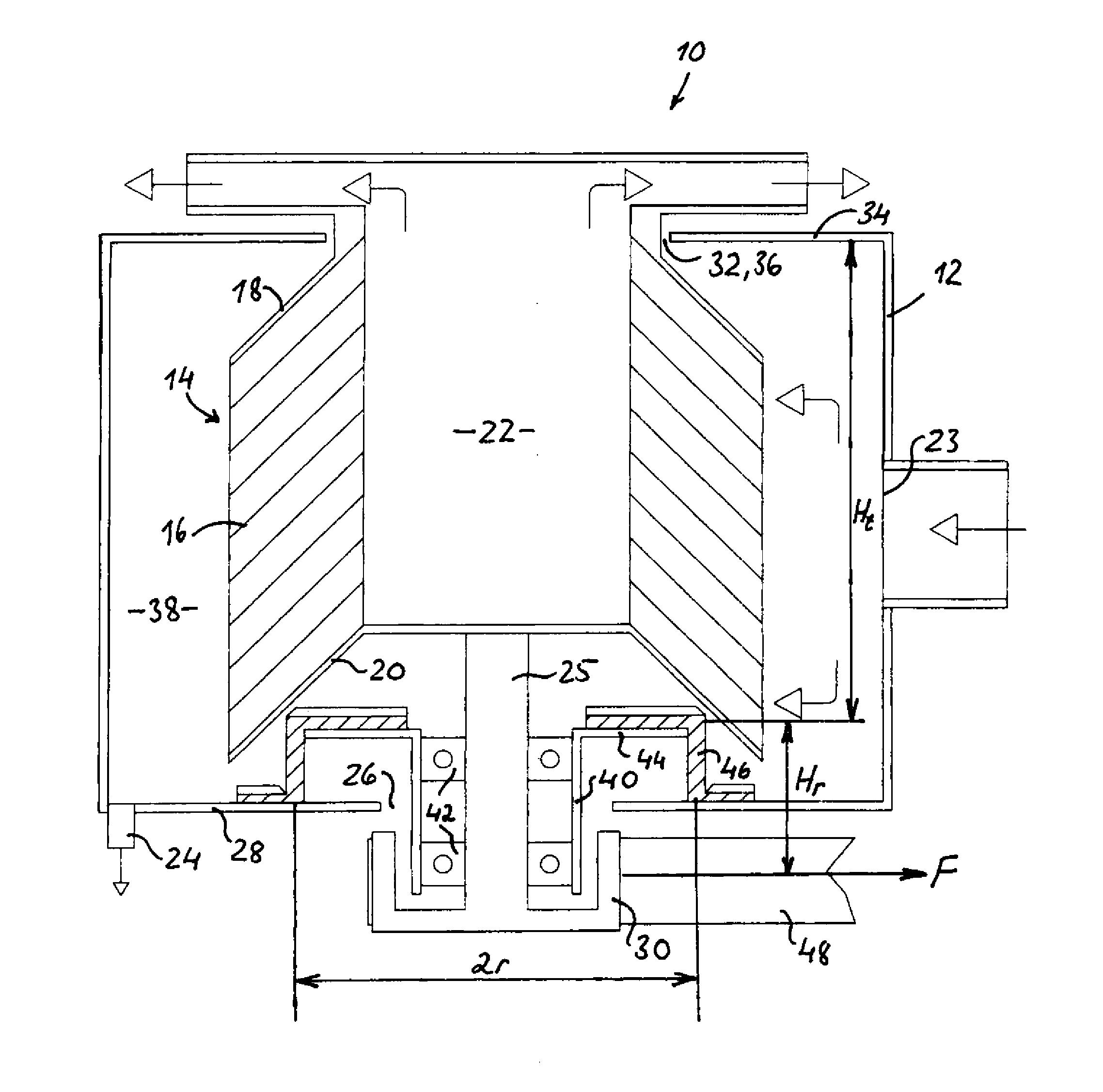
[0020]In FIG. 1 a belt-driven centrifugal separator of the invention for cleaning a gas flow from solid and / or liquid particles therein is generally denoted 10.

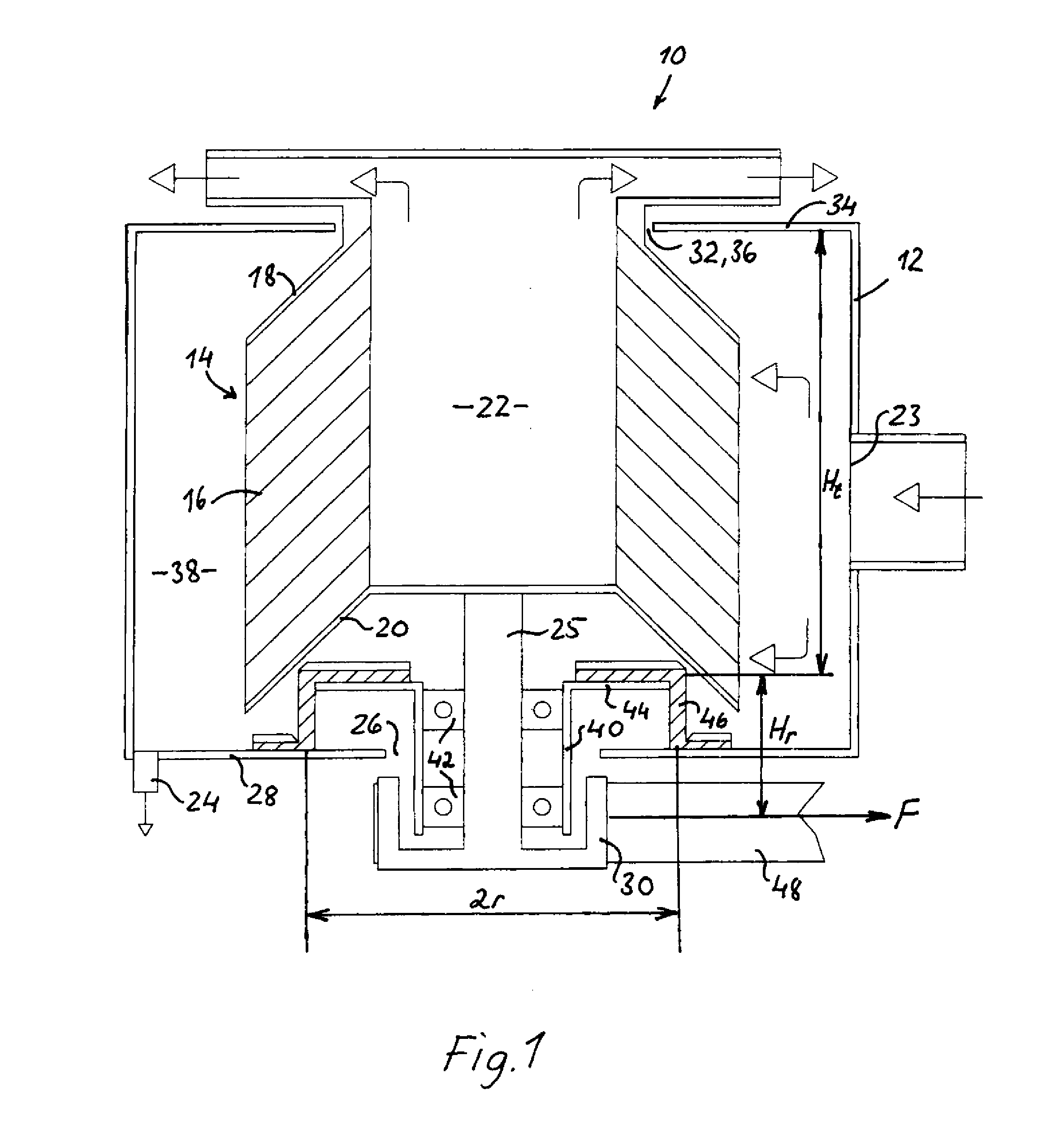
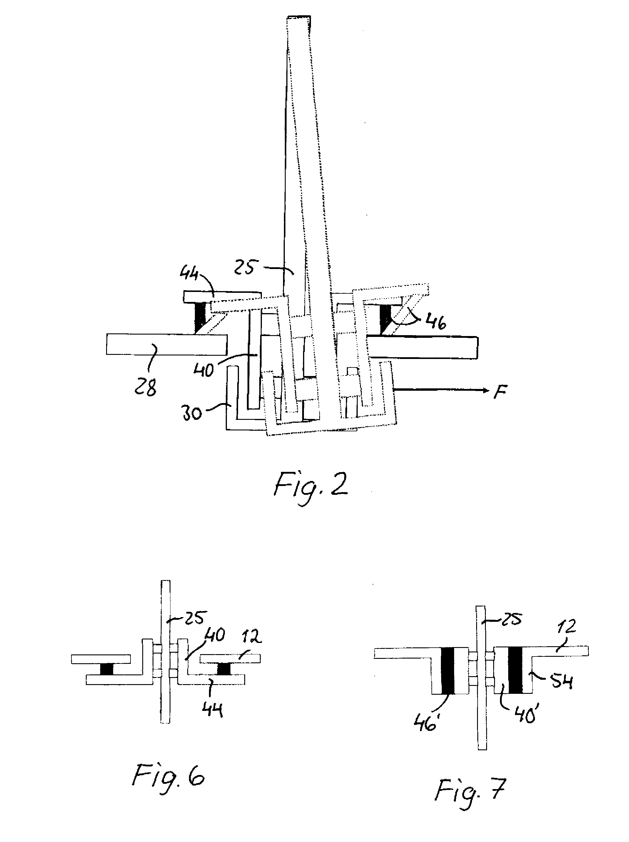
[0021]The separator 10 comprises a stationary casing 12 and a rotor 14 rotatably supported therein. The rotor 14 is, in a manner known per se, formed by a stack of a great number of conical surface elements 16 located at a small mutual axial distance to form narrow flow passages for the gas to be cleaned. The surface elements 16 are held together by an upper and a lower end plate 18 and 20, respectively, and delimit a central flow shaft 22, in the example shown an outlet shaft for the gas flow cleaned by counter-current separation through the rotor. The casing 12 has an inlet opening 23 for the gas to be cleaned, and an outlet 24 for separated particles. The rotor 14 has a drive shaft 25 extending through a passage 26 in a lower wall 28 of the casing 12 and carries a pulley 30 at its lower end. The upper end of the rotor 14 e...


PUM

PropertyMeasurementUnit
Flow rateaaaaaaaaaa
Shapeaaaaaaaaaa
Radiusaaaaaaaaaa

Abstract

Rotor suspension device in a centrifugal separator (10) for cleaning a flow of gas from particles contained therein. The rotor (14) is rotatably supported in a cantilevered manner at one of its ends in a stationary casing (12) by means of a bearing sleeve (40) resiliently connected to the casing (12) by means of an elastic member (46) configured to counteract shearing and tilting movements of the supported end of the drive shaft (25) of the rotor during operation such that the free end of the rotor has a substantially fixed position relative to an upper passage (32) of the casing (12) through which the rotor top extends.

Description

CROSS-REFERENCE TO RELATED APPLICATION[0001]This application is entitled to the benefit of and incorporations by reference subject matter disclosed in International Patent Application No. PCT / EP2012 / 065675 filed on Aug. 10, 2012 and from Swedish Patent Application No. 1150826-4 filed on Sep. 13, 2011.TECHNICAL FIELD [0002]The invention relates to an apparatus for cleaning a flow of gas from solid and / or liquid particles therein by means of centrifugal separation, comprising a rotatable rotor in a surrounding, stationary casing and having a plurality of adjacent surface elements with an inner surface facing the center axis of the rotor onto which surface particles in said gas flow can be trapped by centrifugal forces during the radial passage of the gas flow between the surface elements, said surface elements of the rotor delimiting at least one axial flow shaft in the central portion of the rotor which communicates with the flow passages between the surface elements and with an open...

Claims


Application Information

Patent Timeline
IPC IPC(8): B01D45/14
CPCB01D45/14B04B5/12B04B9/12B04B9/14
Inventor INGE, CLAESFRANZEN, PETER
Owner 3NINE AB
Why Eureka
Try Eureka