Electronic ballast

Active Publication Date: 2014-08-21
PANACEA QUANTUM LEAP TECH
View PDF18 Cites 0 Cited by
  • Summary
  • Abstract
  • Description
  • Claims
  • Application Information

AI Technical Summary

Benefits of technology

The present invention provides a circuit that only requires the connection of two terminals of a lamp, instead of the four terminals used in previous circuits. This results in increased efficiency and reduced waste of power. Additionally, the circuit allows for the adjustment of the output voltage and duty cycle for the load, which can improve performance and reliability.

Problems solved by technology

The power factor correction (PFC) network controls the charge of the capacitor and inductor alternatively, resulting in a permanent and harmonic consumption of the network energy.

Method used


Image

  • Electronic ballast
  • Electronic ballast
  • Electronic ballast

Examples


Embodiment Construction

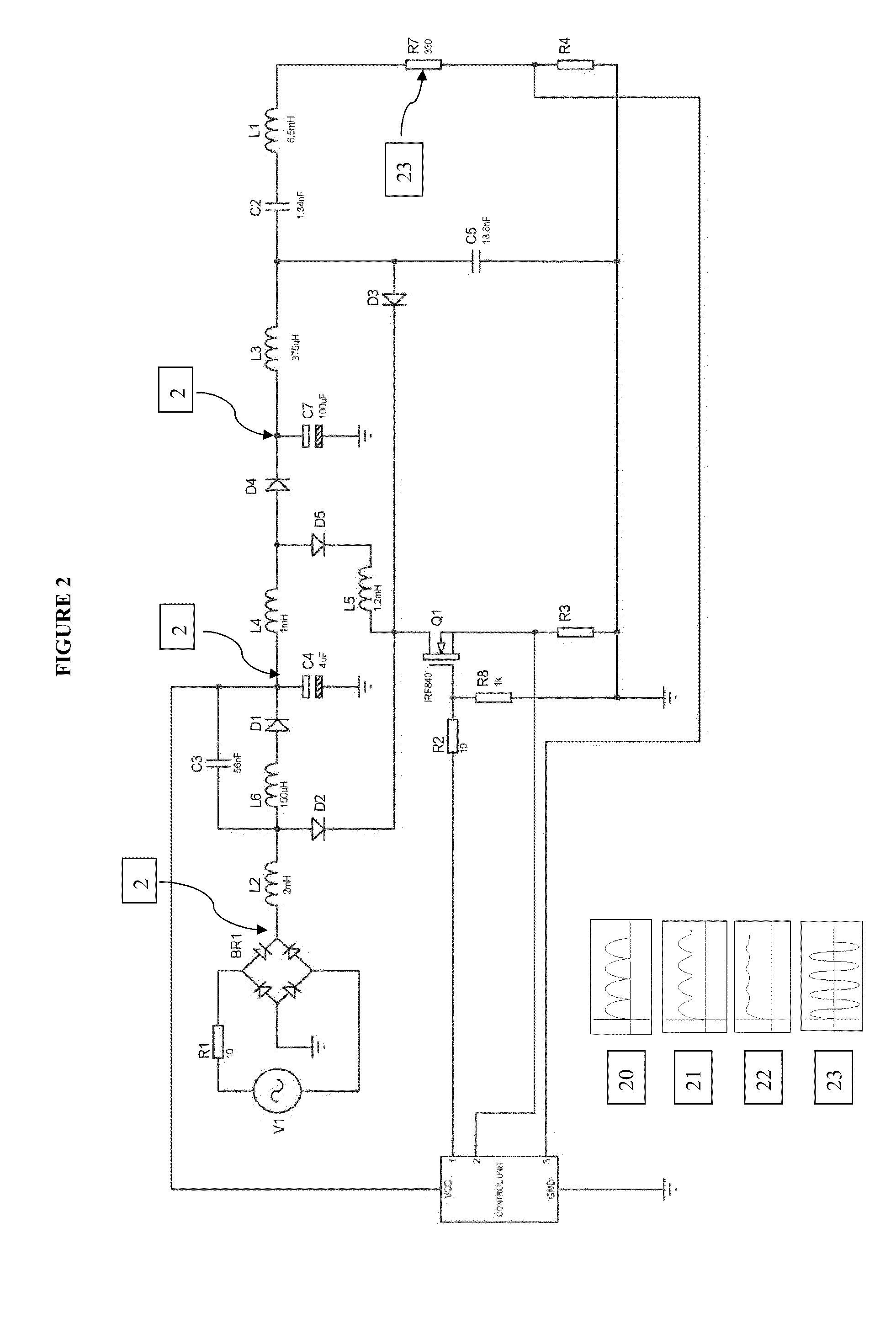
[0016]Referring to FIG. 1, a simplified block diagram of the electronic stages of the electronic ballast (1) of the present invention is shown. The ballast (1) includes a rectifier circuit (2) connected to the network, usually an AC voltage at a frequency of 50 Hz or 60 Hz.

[0017]Whenever it says that a device is connected, coupled, coupled in relation to current or that it may be connected to another device, it means that the device can be directly connected by a wire or as an alternative, get connected through another device such as, but not limited to, a resistor, diode, conductor device, and this connection may be serial or parallel.

[0018]Returning to FIG. 1, the rectifier circuit (2) converts the AC input voltage into a full wave rectified voltage. The rectifier circuit (2) is connected to a power factor correction (PFC) network (3). The power factor correction (PFC) network (3) generates a delay action on the load of one of the components of the circuit to allow smoothing the v...


PUM


Abstract

The present invention discloses an electronic ballast for operating a gas discharge lamp which includes (i) a rectifier bridge circuit; (ii) a power factor correction (PFC) network that includes an electrolytic capacitor that charges by means of a circuit comprised by an inductor, diode and capacitor; and (iii) a switched inverter circuit that converts rectified DC voltage to a high frequency current AC voltage. The electronic circuit has a switch that switches on the aforementioned electronic elements making the (PFC) circuit consume energy continuously from the network, while the electrolytic capacitor remains connected to the voltage of the rectifier bridge, through the inductor and the diode, even if the inductor has no energy stored. From the storage capacitor the inverter is powered by a constant voltage and noise-free, allowing the inverter to power the luminous load properly.

Description

1. FIELD OF THE INVENTION[0001]The present invention relates to electronic ballasts for gas discharge lamps, such as fluorescent lamps.2. DESCRIPTION OF THE STATE OF THE ART[0002]Gas discharge lamps such as fluorescent lamps, generally include a ballast in their circuits, which in addition to generating the starting conditions of the lamp, is responsible for limiting the current to the load. The initial voltage or starting voltage is higher than the sustainability voltage; the ballast must be designed to handle various events, preserving the largest possible transfer of power to the load, with the most harmonious and appropriate treatment of the supply network and the lamp load. The impedance of the discharge lamp tends to an infinite value at shutdown conditions, but once the arc is generated when the gas is ionized inside the lamp, it changes of impedance until the lamp starts, wherein its impedance tends to zero, so that a current limiter element is incorporated between the netwo...

Claims


Application Information

Patent Timeline
IPC IPC(8): H05B37/02
CPCH05B37/02H05B41/28H05B45/355H05B45/39H05B47/10Y02B20/30
Inventor VELASCO VALCKE, FRANCISCO JAVIER
Owner PANACEA QUANTUM LEAP TECH
Why Eureka
Try Eureka