
System and method of relay communication with electronic beam adjustment

a relay communication and beam adjustment technology, applied in the field of radio communication technology, can solve the problems of additional problems in their operation not occurring in antenna systems with lower carrier frequency and bandwidth, high buildings are also subject to the same problems, and achieve the effect of less possibility of errors and better data transmission accuracy

Active Publication Date: 2014-08-14
OBSHCHESTVO S OGRANICHENNOJ OTVETSTVENNOSTYU RADIO GIGABIT
View PDF6 Cites 248 Cited by
  • Summary
  • Abstract
  • Description
  • Claims
  • Application Information

AI Technical Summary

Benefits of technology

The patent describes a way to adjust the beam of an antenna using electronic scanning, which eliminates the need for expensive equipment like cameras and power detectors. Electronic scanning also makes it easier to position the antenna and automatically track and adjust it for optimal performance. The invention also ensures reliable data transmission between two transceivers.

Problems solved by technology

The transmit power is typically limited by the regulations that leaves the only option of increasing the antenna gain.
The use of antennas with such narrow beam widths in the radio relay systems leads to additional problems in their operation not occurring in antenna systems with lower carrier frequency and bandwidth.
High buildings are also subject to the same problems (though at a less extent) because of low drifts of their bases that leads to small changes of the building orientations especially closer to the roof level.
Such changes of the orientations of the mounting constructions may lead to loss of the mutual orientation of the transmitter and receiver antennas and failure of the communication link.
This problem became now acute for millimeter-wave radio relay systems where the beam widths of the used antennas are about 1 degree or below because of the reasons considered above.
The use of phased antenna arrays is however impractical nowadays for the millimeter-wave relay systems due to the very large antenna elements number requirement.
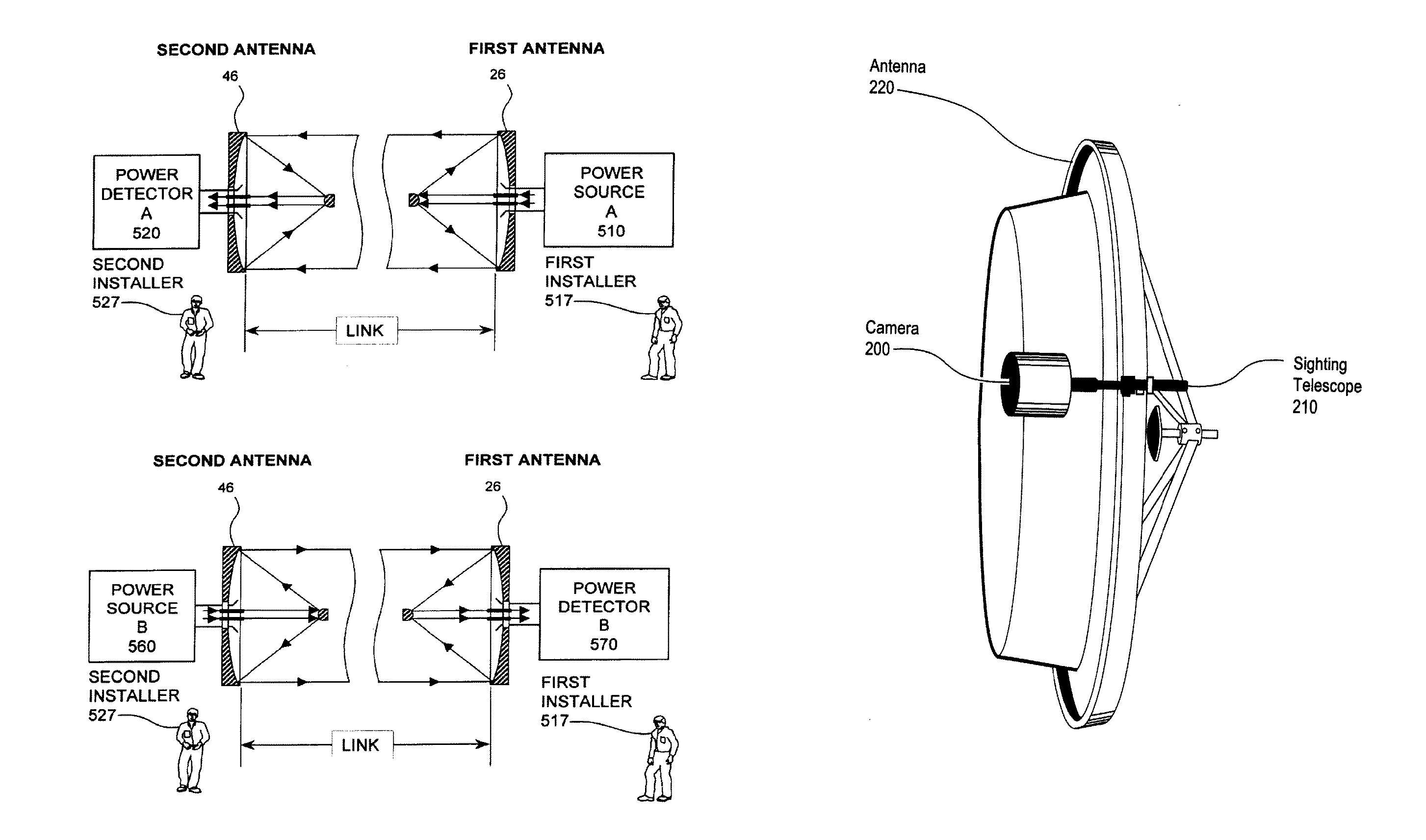
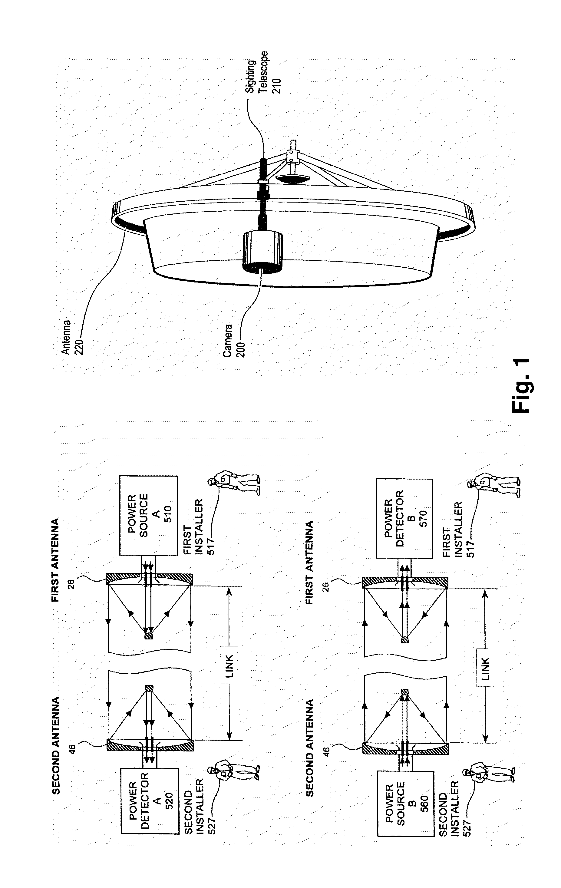
The above mentioned modern methods of mechanical scanning include rotation of the whole antenna using precise mechanisms, movement or rotation of primary antenna elements of the reflectors, movement of the secondary comparatively small reflector of, for example, Cassegrain antenna, usage of multi-aperture antennas together with the array of switched antenna elements and are far from being optimal.
All methods of mechanical scanning are comparatively slow and can require the manual work using qualified staff.
However, this system requires the use of expensive precise motor technique and a computer system for signal processing controlled by a qualified operator.
However, the system described in U.S. Pat. No. 6,587,699 requires the use of additional expensive equipment integrated into the relay system structure and elaborative work of specially qualified staff in the initial antenna beam adjustment procedure and thus, is expensive.
The mentioned control unit can lead to low efficiency of electronic beam adjustment and possibility of introducing of mistakes due to the ability to only enlarge the radiation pattern beam at the cost of the antenna gain.

Method used


Image

  • System and method of relay communication with electronic beam adjustment
  • System and method of relay communication with electronic beam adjustment
  • System and method of relay communication with electronic beam adjustment

Examples


Embodiment Construction

[0070]The present invention relates to transceivers for a point-to-point millimeter wave communication system with electronically adjustable antennas, to point-to-point millimeter wave communication systems with electronically adjustable antennas consisting of a plurality of the mentioned transceivers, and to methods for mutual alignment of antennas in a point-to-point millimeter wave communication system with electronically adjustable antennas.

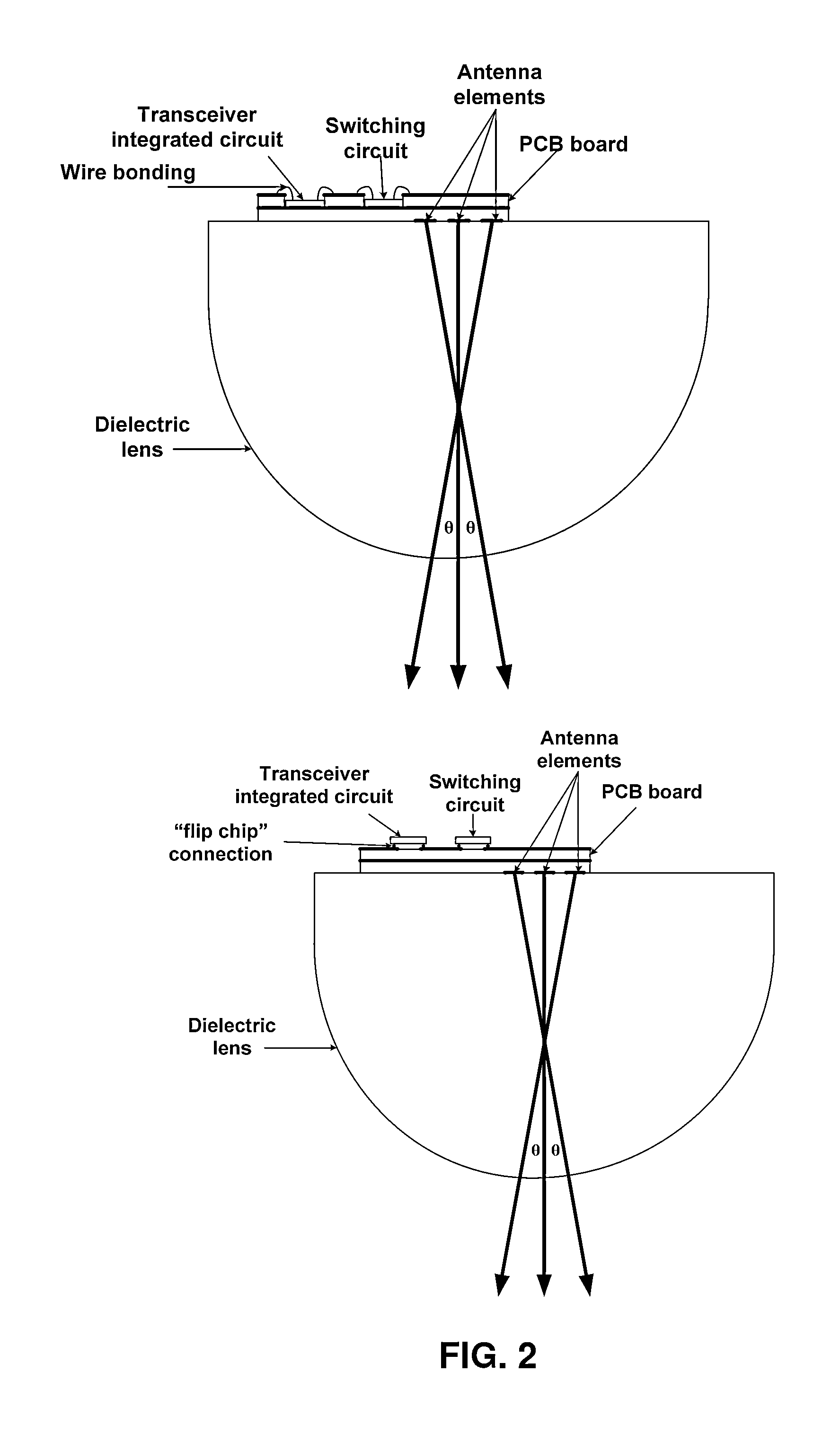
[0071]According to one embodiment of the claimed invention, highly directive antennas are used in each of the relay system transceivers. The highly directive antennas are capable of electronically switch between beam directions in a continuous angle range wider than the antenna beam width. Herewith the electronic scanning can be provided in different antenna types such as reflector antennas, lens antennas, integrated lens antennas, etc. The antennas should be designed to provide switching between feed antenna elements in the array located in ...


PUM


Abstract

The invention relates to millimeter-wave point-to-point communication systems. A system comprises two separated millimeter-wave transceivers which provide high throughput data transmission and reception in frequency duplex mode and use high gain antennas capable of electronic scanning in some continuous angle range provided by the control module that implement control algorithms for antenna radiation pattern. Also a method based on the exploitation of scanning antennas of initial beam directions fine adjustment and subsequent beam directions tracking and readjustment when needed is proposed.The proposed system and method provide automatic recovery of failed connection in case of relay station orientation change due to influence of various external factors (wind, vibration, different intensity of heating of the bracing mountings at different time of a day and others) and can be used in backhaul systems of base station sites for mobile networks.

Description

CROSS-REFERENCE TO RELATED APPLICATIONS[0001]This application is a continuation-in-part of International application No. PCT / RU2011 / 000814, the content of which is incorporated herein by reference in its entirety.BACKGROUND OF THE INVENTION[0002]1. Field of the Invention[0003]The present invention generally relates to the field of radio communication technology and, more particularly, to high throughput millimeter-wave point-to-point radio relay communication systems. The present invention represents a system and method of relay communication with electronic beam adjustment. The present invention provides both automatic initial alignment of antenna beam directions of two radio relay stations as well as further adjustment of beam directions to compensate for small antenna orientation changes caused by various factors (such as wind, vibration, different expansion coefficients of the bearing structures at temperature fluctuations, etc).[0004]2. Description of Related Art[0005]Point-to-...

Claims


Application Information

Patent Timeline
Patent Type & Authority Applications(United States)
IPC IPC(8): H04B7/155
CPCH04B7/155H01Q1/1257H01Q3/245H01Q25/007H01Q1/12
Inventor ARTEMENKO, ALEKSEY ANDREEVICHMASLENNIKOV, ROMAN OLEGOVICH
Owner OBSHCHESTVO S OGRANICHENNOJ OTVETSTVENNOSTYU RADIO GIGABIT
Learn More