Eureka AIR delivers breakthrough ideas for toughest innovation challenges, trusted by R&D personnel around the world.

Light unit and a LCD liquid crystal display comprising the light unit

Active Publication Date: 2014-08-14
LG INNOTEK CO LTD
View PDF10 Cites 3 Cited by
  • Summary
  • Abstract
  • Description
  • Claims
  • Application Information

AI Technical Summary

Benefits of technology

The present invention is about improving the quality of light emitted from a light unit. It does this by creating a pattern on the surface of a light diffusion plate that shields or diffuses light. This pattern combines a diffusion pattern and a metal pattern to make the light look uniform and to block yellow light. This results in a better quality light output. Additionally, this invention eliminates the need for a separate light guide plate and uses a film-type resin layer to guide the light, reducing the number of light sources and making the back-light unit thinner and more flexible. The invention also includes a side view LED that remarkably reduces the number of light sources and achieves optical characteristics. Overall, this invention improves the efficiency and quality of light emitted from a light unit.

Problems solved by technology

However, the conventional light unit is problematic in that it is difficult to achieve thinness of an entire product because of the thickness of the light guide plate, and an image quality may be deteriorated in the case of a large-area back-light unit.
However, the optical pattern using Ag for obtaining the light shielding effect has a drawback in that a portion having the pattern is completely optically shielded, so that it is difficult to attain uniformity of light through an entire portion, and reliability of the light unit emitting white light is lowered because of yellow light emitted from the light source, the LED.

Method used


Image

  • Light unit and a LCD liquid crystal display comprising the light unit
  • Light unit and a LCD liquid crystal display comprising the light unit
  • Light unit and a LCD liquid crystal display comprising the light unit

Examples


Embodiment Construction

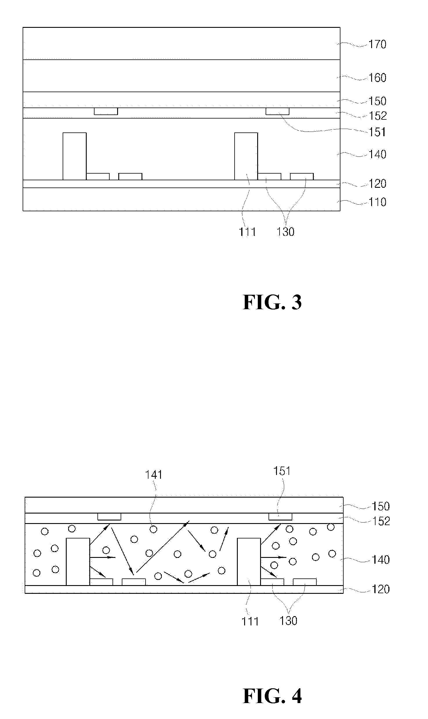
[0035]Exemplary embodiments of the present invention will be described below in detail with reference to the accompanying drawings. Wherever possible, the same reference numerals will be used to refer to the same elements throughout the specification, and a duplicated description thereof will be omitted. It will be understood that although the terms “first”, “second”, etc. are used herein to describe various elements, these elements should not be limited by these terms. These terms are only used to distinguish one element from another element.

[0036]The present invention is directed to a back-light unit, which forms a diffusion plate having an optical pattern layer for efficiently shielding or diffusing light, thus enhancing optical efficiency, and eliminates a light guide plate from a conventional light unit and forms a resin layer in place of the light guide plate, thus remarkably reducing an entire thickness of the back-light unit, and can reduce the number of light sources. Parti...


PUM


Abstract

Provided is a light unit including a plurality of LED light sources formed on a PCB, a resin layer stacked on the PCB to diffuse and guide emitted light forwards, and a diffusion plate having an optical pattern printed thereon to shield light emitted from the LED light sources. The optical pattern is composed of a diffusion pattern implemented as at least one layer, or a combination of the diffusion pattern layer and a light shielding pattern. The light unit forms an optical pattern for shielding or diffusing light on a surface of a light diffusion plate of the back-light unit, and combines a diffusion pattern and a metal pattern to attain uniformity of light and realize a yellow-light shielding effect, thus leading to a reliable light quality.

Description

CROSS-REFERENCE TO RELATED APPLICATIONS[0001]This application is the U.S. national stage application of International Patent Application No. PCT / KR2011 / 006739, filed Sep. 9, 2011, the disclosure of which is incorporated herein by reference in its entirety.TECHNICAL FIELD[0002]The present invention relates to a light unit eliminating a light guide plate and having a diffusion plate on which an optical pattern for increasing light shielding and haze effects is formed.BACKGROUND ART[0003]In general, a liquid crystal display (LCD) is a device that individually supplies a data signal based on image information to pixels arranged in a matrix array and adjusts optical transmittance of the pixels to form a desired image. Since LCD cannot emit light by itself, a light unit is mounted to a rear of the LCD to produce an image.[0004]Referring to FIG. 1, such a light unitl is configured so that a flat light guide plate 30 is placed on a substrate 20 and a plurality of side view LEDs 10 (only one...

Claims


Application Information

Patent Timeline
IPC IPC(8): G02F1/1335
CPCG02F1/133603G02B6/0021G02B6/0041G02B6/0051G02B6/0055
Inventor PARK, KWANG HOCHANG, WOO YOUNGKIM, CHUL HONGLEE, BYOUNG EON
Owner LG INNOTEK CO LTD
Why Eureka
Eureka Blog
Learn More