
Rear sealing head heat-insulation layer structure for solid rocket engine and forming method of rear sealing head heat-insulation layer structure

A solid rocket and molding method technology, applied in rocket engine devices, machines/engines, mechanical equipment, etc., can solve the problems of interface combination bonding reliability is not as good as direct molding, cannot take into account comprehensive advantages, and has many molding processes. The effect of improving thermal protection performance, excellent comprehensive performance and simple molding method

Active Publication Date: 2019-06-04
HUBEI INST OF AEROSPACE CHEMOTECH
View PDF6 Cites 6 Cited by
  • Summary
  • Abstract
  • Description
  • Claims
  • Application Information

AI Technical Summary

Problems solved by technology

[0003] At present, the structure design and process molding of the heat insulation layer of the rear head generally use a single material to form, which cannot take into account the comprehensive advantages, or use different functional materials to form, need to form different functional materials separately, and then bond and assemble after processing separately. There are many forming processes. The processing cycle is long, the cost is high, and the reliability of interface combination bonding is not as high as that of direct molding.

Method used


Image

  • Rear sealing head heat-insulation layer structure for solid rocket engine and forming method of rear sealing head heat-insulation layer structure
  • Rear sealing head heat-insulation layer structure for solid rocket engine and forming method of rear sealing head heat-insulation layer structure
  • Rear sealing head heat-insulation layer structure for solid rocket engine and forming method of rear sealing head heat-insulation layer structure

Examples


Embodiment 1

[0025] Embodiment 1 A solid rocket motor rear head heat insulation layer structure and its forming method

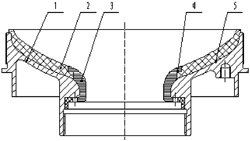
[0026] Such as figure 1 and figure 2 As shown, the heat insulation layer structure of the rear head of a solid rocket motor according to the present invention includes a heat insulation body, a lightweight rubber heat insulation layer 2 and an anti-ablation and anti-scouring heat insulation layer 3, wherein the heat insulation body 1 is used as a structural support, The lightweight rubber insulation layer 2 is arranged and distributed at the converging large end of the heat insulation body, and the anti-ablation and anti-scouring heat insulation layer 3 is arranged and distributed at the convergent narrow passage of the heat insulation body. For lap joints, the light rubber-type heat insulating layer and the anti-ablation and anti-erosion heat insulating layer are respectively preformed and placed on the heat insulating body for one-time thermosetting molding to form a...

Embodiment 2

[0032] Embodiment 2 A solid rocket motor rear head heat insulation layer structure and its forming method

[0033] The structure of the thermal insulation layer of the rear head of the solid rocket motor is the same as that in Embodiment 1. In the present invention, the lightweight thermal insulation material is EPDM rubber thermal insulation material; the anti-ablation and anti-scouring thermal insulation material is ablation-resistant fiber or fabric, and the body is made of metal.

[0034] A method for forming the heat insulation layer of the rear head of the above-mentioned solid rocket motor, which specifically includes the following steps:

[0035] 1) Preform the unvulcanized low-density rubber-type thermal insulation material, the preforming temperature is 50°C, the time is 3min, and the pressure is 5Mpa calculated according to the pressure bearing area of ​​the preforming mold and the pressure of the equipment;

[0036] 2) Preform the uncured thermal insulation materi...

Embodiment 3

[0039] Embodiment 3 A solid rocket motor rear head heat insulation layer structure and its forming method

[0040] The structure of the thermal insulation layer of the rear head of the solid rocket motor is the same as that in Embodiment 1. In the present invention, the lightweight heat insulating material is nitrile rubber heat insulating material; the anti-ablation and anti-scouring heat insulating material is high silica fiber or fabric, and the body is made of metal.

[0041] A method for forming the heat insulation layer of the rear head of the above-mentioned solid rocket motor, which specifically includes the following steps:

[0042] 1) Prefabrication of unvulcanized low-density rubber-type thermal insulation material, the preformation temperature is 90°C, the time is 10min, and the pressure is 20MPa calculated according to the pressure bearing area of ​​the preformation mold and the pressure of the equipment;

[0043] 2) Preform the uncured thermal insulation materia...


PUM


Abstract

The invention discloses a rear sealing head heat-insulation layer structure for a solid rocket engine and a forming method of the rear sealing head heat-insulation layer structure, and belongs to thefield of design and manufacturing of heat insulation layers of heat protection structures for solid rocket engines. At present, a rear sealing head heat-insulation layer structure difficulty meets theuse requirements for light weight, ablation resistance, scouring resistance, high-efficiency manufacturing and low cost simultaneously. According to the rear sealing head heat-insulation layer structure, a heat-insulation body serves as a structural support, pre-formed light rubber heat-insulation materials are arranged and distributed at a large convergence end, pre-formed curing resin heat-insulation materials are arranged and distributed at a narrow convergence channel, the connection positions are in transition butting and lapping through stair-type steps, and overall one-time heat-curingforming is conducted to form an integrated structure through a forming mold tool. Practice proves that all interfaces of the rear sealing head heat-insulation layer structure prepared through the forming method are bonded reliably, the forming efficiency is high, comprehensive performance of a product is good, and the comprehensive use requirements of the rear sealing head heat-insulation structure for the engine can be simultaneously met well.

Description

technical field [0001] The invention belongs to the field of design and manufacture of a thermal insulation layer of a thermal protection structure of a solid rocket motor, and relates to a structure and a forming method of a thermal insulation layer of a rear head of a solid rocket motor. Background technique [0002] With the traction of high-performance and low-cost use of solid rocket motors, the design and molding methods of its thermal protection structures are increasingly required to have reliable adaptability. As an important structural part of the solid rocket motor, the rear head generally has to withstand the ablation of the high-temperature and high-speed gas flow of the engine and the more severe rapid erosion at the convergence point. The engine structural parts should be as light as possible while meeting the usage requirements; the manufacturing process should be as high-quality, efficient and low-cost as possible. [0003] At present, the structure design ...

Claims


Application Information

Patent Timeline
IPC IPC(8): F02K9/32B29C35/02
Inventor 彭正贵丁礼平王江李月常詹穹赵志祥方陆军李洋
Owner HUBEI INST OF AEROSPACE CHEMOTECH
Learn More