
Device for injecting and mixing fluids in a downward-flow reactor

a technology of fluid injection and downward flow, which is applied in the direction of hydrocarbon oil cracking, catalytic naphtha reforming, chemical/physical/physicochemical processes, etc., can solve the problems of non-selective reactions, large volume, and prematurely reducing the activity of catalysts

Active Publication Date: 2014-08-14
INST FR DU PETROLE
View PDF1 Cites 165 Cited by
  • Summary
  • Abstract
  • Description
  • Claims
  • Application Information

AI Technical Summary

Benefits of technology

The patent is about a new catalytic reactor design that allows for efficient mixing of fluids. The reactor includes a chamber with two solid catalyst beds separated by an intermediate zone, a device for mixing fluids, and an annular mixing chamber located below the chamber. The reactor is characterized by a tubular portion that empties into a vertical collecting pipe, and a predistribution plate with perforations and a shaft. The reactor can be used in a process where a quenching fluid is injected. The technical effects of this design include improved fluid mixing, reduced pressure drop, better temperature control, and improved reaction efficiency.

Problems solved by technology

These hot points can prematurely decrease the activity of the catalyst.
They also lead to non-selective reactions.
This device makes it possible to remedy certain drawbacks of the different systems of the prior art but remains very bulky.

Method used


Image

  • Device for injecting and mixing fluids in a downward-flow reactor
  • Device for injecting and mixing fluids in a downward-flow reactor
  • Device for injecting and mixing fluids in a downward-flow reactor

Examples


Embodiment Construction

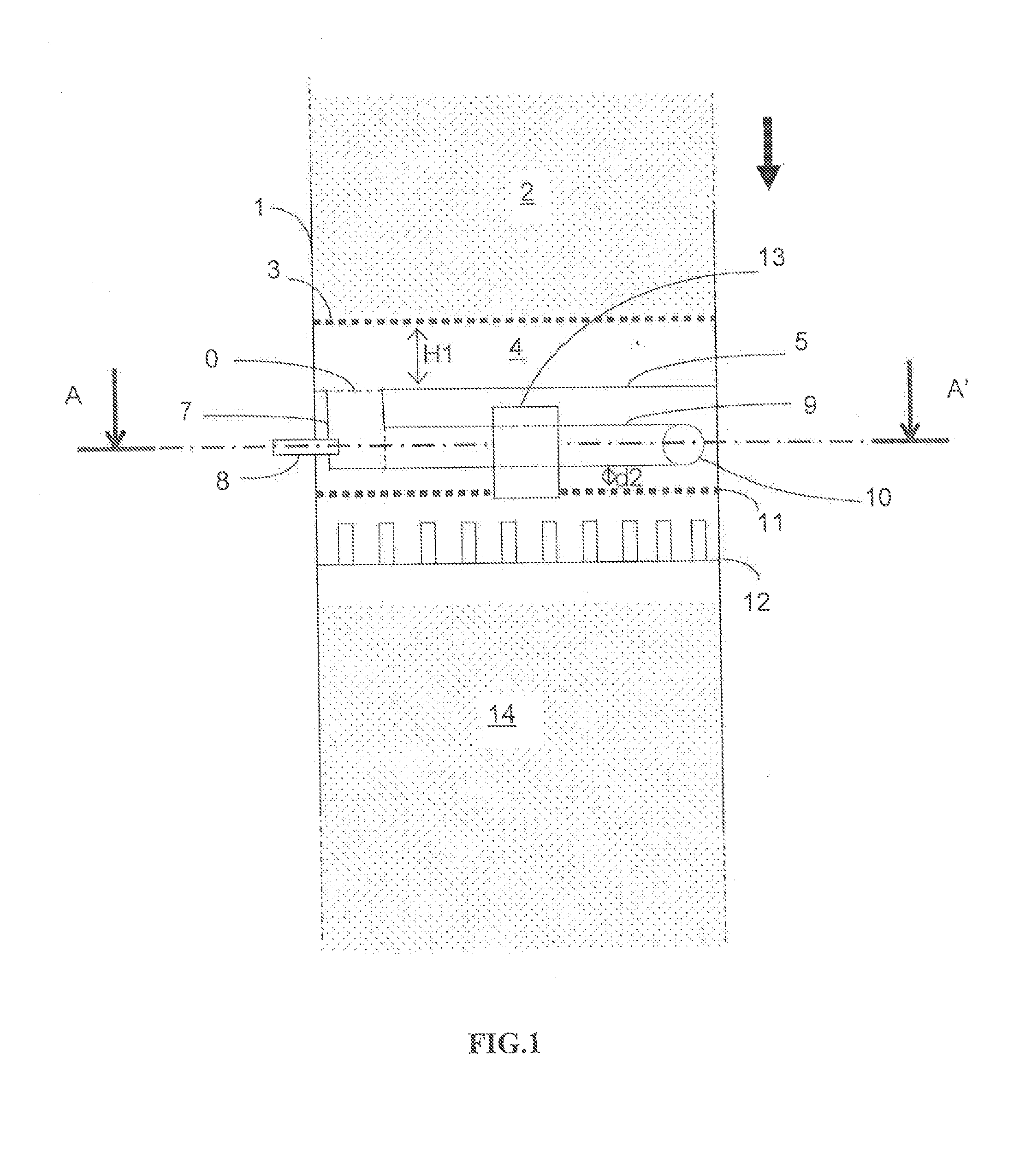
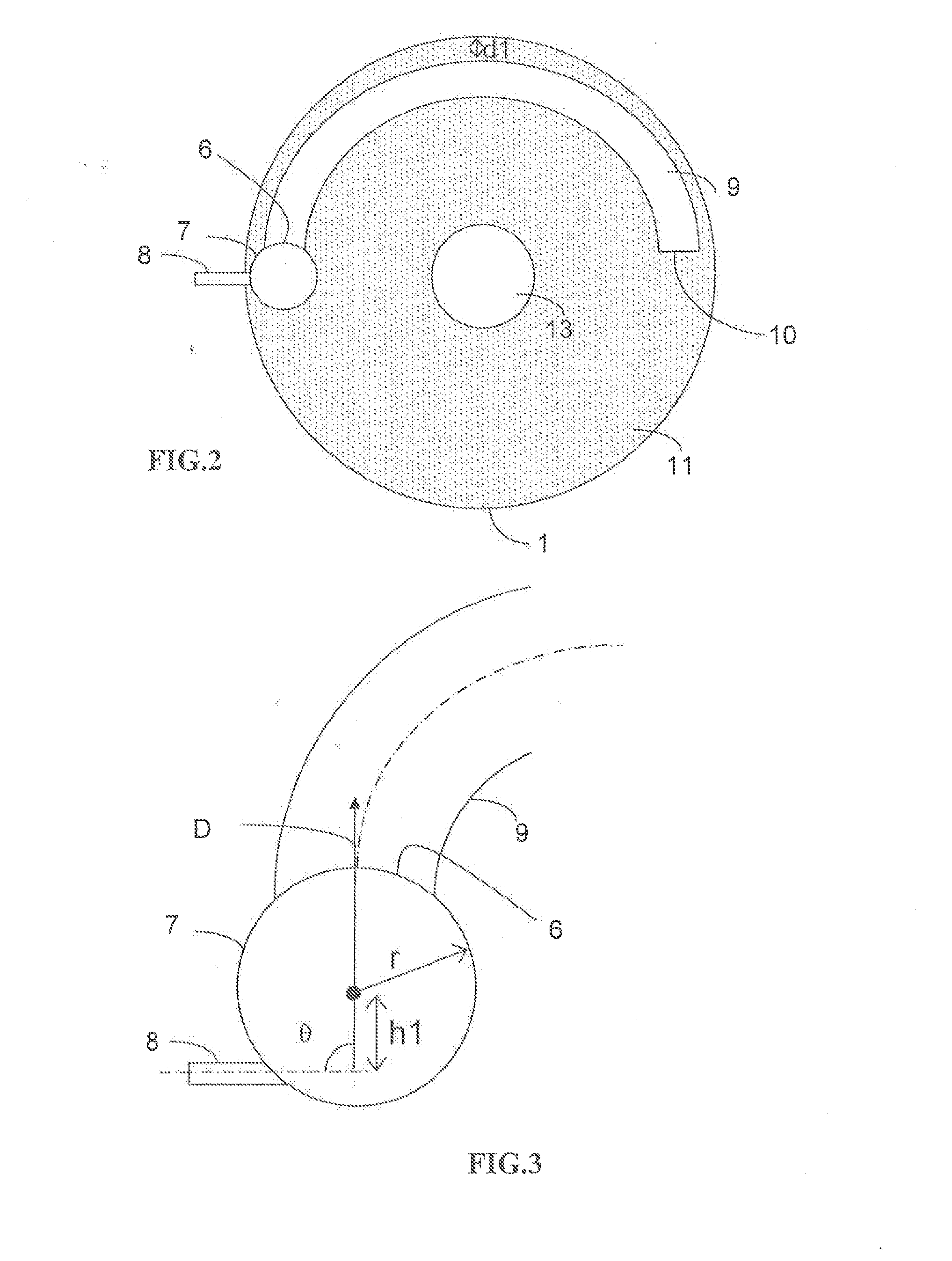
[0031]FIG. 1 shows a reactor portion according to an embodiment of the invention, in which exothermic reactions, such as reactions of hydrotreatment, hydrodesulfurization, hydrodenitration, hydrocracking, hydrogenation, and hydrodearomatization, are carried out. The reactor consists of a chamber 1 that contains at least one solid catalyst bed 2. In general, the chamber has an elongated shape along an essentially vertical axis. For example, the chamber 1 has the shape of a cylinder that is closed at its ends, with the axis of the cylinder being oriented in a vertical direction. The cylinder can have a diameter of between 1 and 10 meters, and a height of between 3 and 20 meters. The reactor is supplied in the upper part with reaction fluid, composed of a gas or a liquid or a mixture containing liquid or gas, for example a hydrocarbon feedstock that is at least partly liquid and gaseous hydrogen. The reaction fluid (or process fluid, in English terminology) is made to circulate, in par...


PUM


Abstract

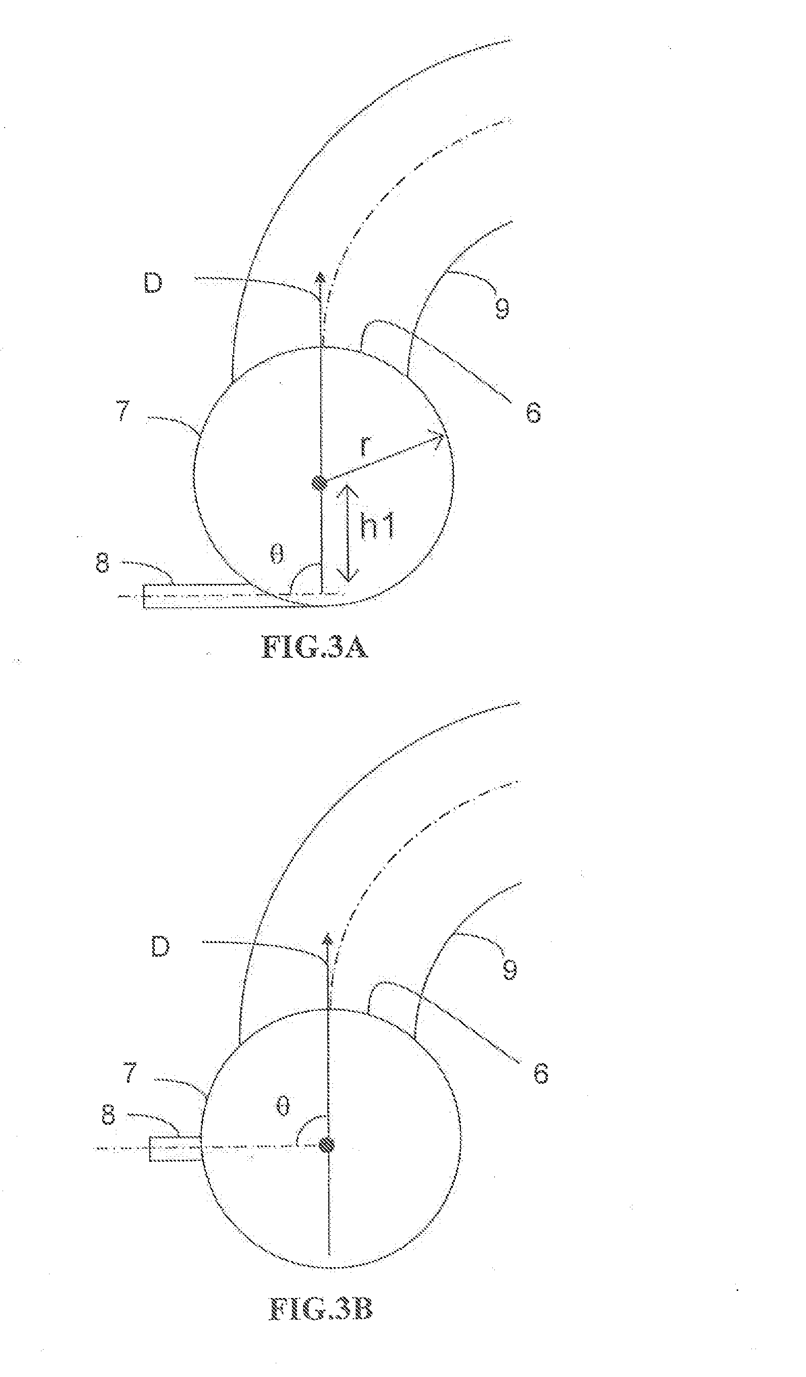
The catalytic reactor with downward flow comprises a chamber (1) containing at least two solid catalyst beds (2; 11) separated by an intermediate zone comprising an essentially horizontal collecting plate (5) communicating with a vertical collecting pipe (7) for receiving fluids collected by the collecting plate, with a means for injecting a quenching fluid (8) emptying into the collecting pipe. An annular mixing chamber (9) is located below the collecting plate (5). A predistribution plate (11) is arranged below the chamber (9).The injection means (8) comprises a tubular portion that empties into the collecting pipe (7) in such a way as to inject quenching fluid in a direction forming an angle θ between 45° and 135° with the direction D from the axis of the mixing chamber measured at its input end.

Description

FIELD OF THE INVENTION[0001]The invention applies within the field of exothermic reactions and more particularly to reactions of hydrotreatment, hydrodesulfurization, hydrodenitration, hydrocracking, hydrogenation, and hydrodearomatization carried out in a reactor. This invention relates to a device for injecting and mixing a quenching fluid in a downward-flow reactor and its use for implementing exothermic reactions. The invention also relates to a reactor that comprises a compact mixing device.EXAMINATION OF THE PRIOR ART[0002]The exothermic reactions carried out in refining and / or in petrochemistry require being cooled by an additional fluid to prevent a heat excursion from the reactor in which they are carried out. It is also necessary to keep a homogeneous temperature gradient within the reactor so as to prevent the existence of hot points in the catalyst bed. These hot points can prematurely decrease the activity of the catalyst. They also lead to non-selective reactions. It i...

Claims


Application Information

Patent Timeline
Patent Type & Authority Applications(United States)
IPC IPC(8): B01J19/18
CPCB01J19/1862B01J8/0492B01J8/0496B01J8/0453B01J2208/00362B01J2208/00371
Inventor HAROUN, YACINEAUGIER, FREDERIC
Owner INST FR DU PETROLE
Learn More