
Capillary microcuvette having double loading means

a microcuvette and loading means technology, applied in the field of microcuvettes, can solve the problems of inconvenient use of a finger of the subject, difficult use of conventional microcuvettes with blood samples, and inconvenient use of conventional microcuvettes as described above, so as to improve the convenience and accuracy of measurement for the user

Active Publication Date: 2014-08-07
BODITECHMED
View PDF4 Cites 22 Cited by
  • Summary
  • Abstract
  • Description
  • Claims
  • Application Information

AI Technical Summary

Benefits of technology

The present invention is a microcuvette that improves the user's convenience and accuracy of measuring by providing two ways to apply blood samples: directly from finger tips or using a pipette from a collection tube. This allows for easier and more flexible application of samples. Additionally, the microcuvette allows for any amount of sample to be loaded as long as it fills the cavity by capillary action. These features make the microcuvette more user-friendly and efficient for measuring samples.

Problems solved by technology

However, the problem with the conventional microcuvette is that it can apply the blood specimen only through the sample inlet formed therein.
This has resulted in the inconvenience that a finger of the subject needs to be aligned with the narrow sample inlet to apply blood to the microcuvette.
The conventional microcuvette is particularly inconvenient because the capillary force to introduce the sample into the detection zone is only generated at a restricted area of the narrow sample inlet.
Further, the conventional microcuvette as described above becomes more difficult to use with blood samples collected beforehand and kept in a tube.
However the conventional microcuvette has a structure that is not very much compatible with the micropipettes.
However, the former extra procedure as described above may cause biohazardous problems if a blood sample is spilled out during the process.
The latter, though it removes a risk of blood spills, may also cause a contamination problem during the process.

Method used


Image

  • Capillary microcuvette having double loading means
  • Capillary microcuvette having double loading means
  • Capillary microcuvette having double loading means

Examples


Embodiment Construction

Problems to be Solved

[0009]To solve the problems as described above, the purpose of the present invention is to provide a microcuvette for optical analysis of the specimen in which direct introduction or loading of the sample from the source such as fingertip to the microcuvette or the introduction using micropipettes can be more conveniently performed.

SUMMARY OF THE INVENTION

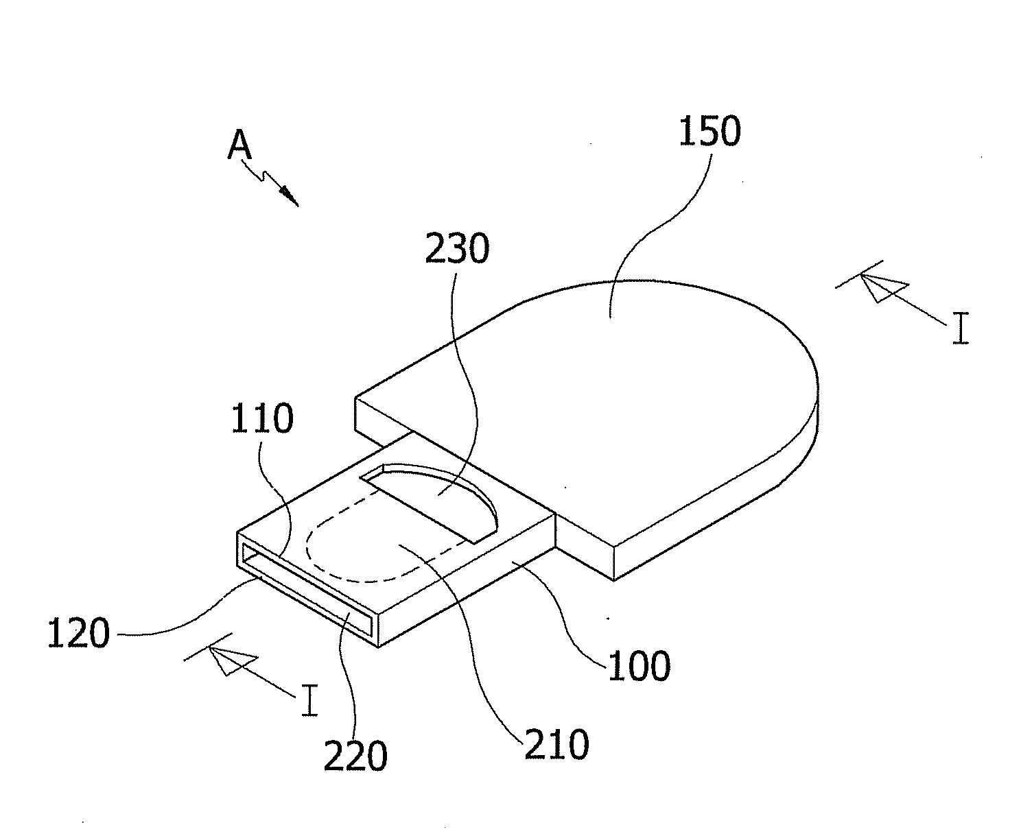
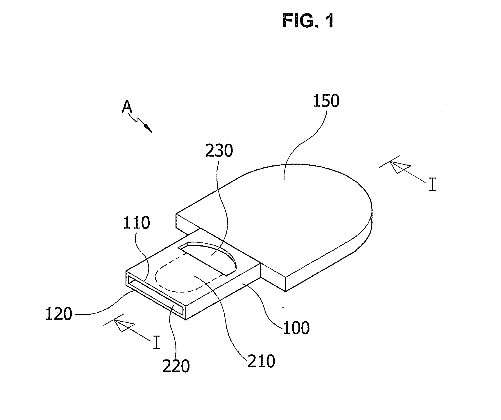
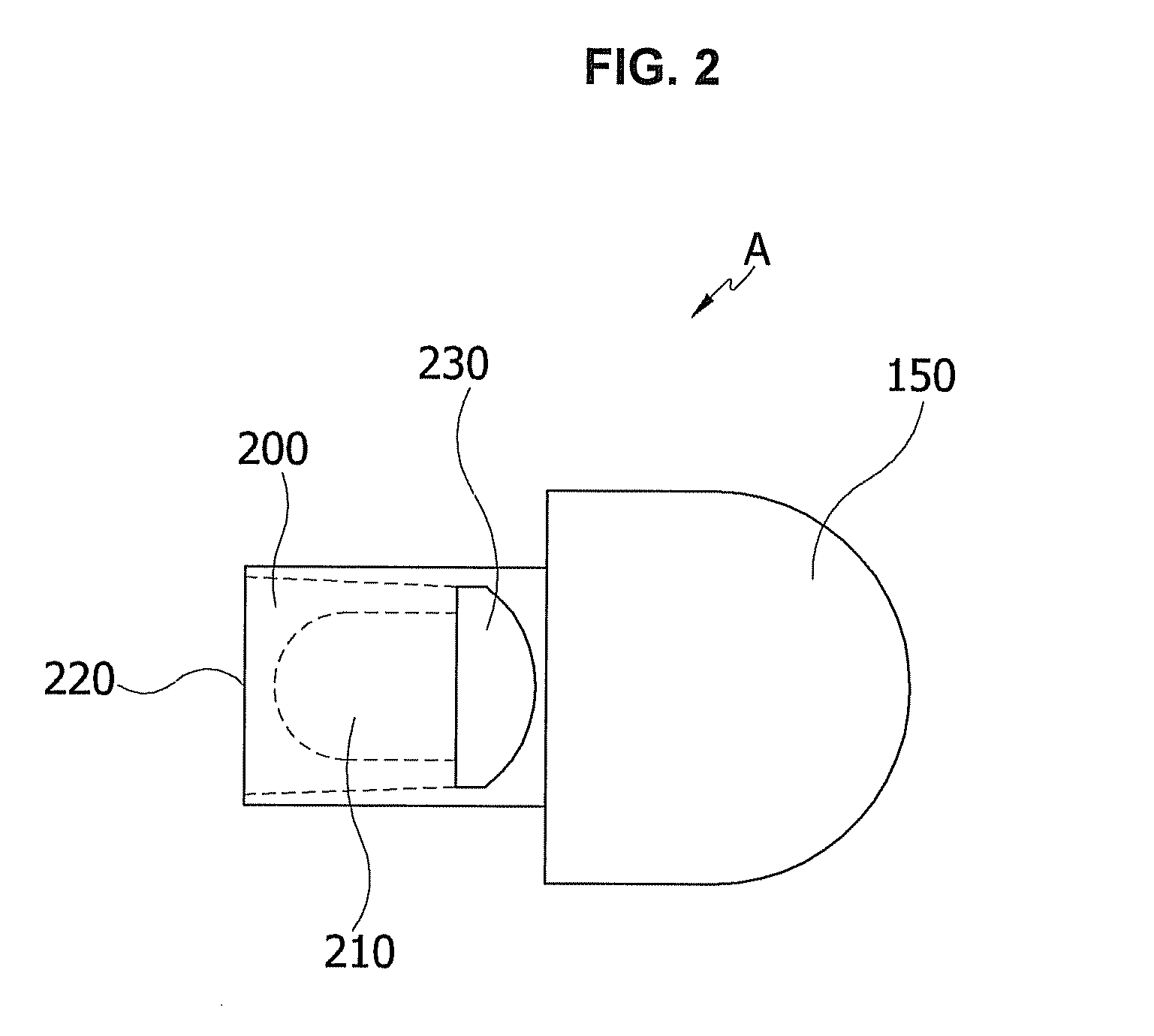
[0010]In one aspect, the present disclosure provides a microcuvette for optical analysis of a sample comprising: a body member comprising two planar plates; and a cavity formed within the body member, the cavity being defined by the two opposing inner surfaces of the plates of the body member, a portion of the cavity defining a detection zone, the body member comprising an end portion, a capillary inlet being provided at the end portion and that is communicated with the cavity, a sample slot being provided at a portion of the body member in which the capillary inlet is not formed, the sample slot being communic...


PUM

PropertyMeasurementUnit
lengthaaaaaaaaaa
lengthaaaaaaaaaa
optical analysisaaaaaaaaaa

Abstract

The present invention relates to a capillary microcuvette, the microcuvette comprises a body member having two plates and a cavity formed within the body, the cavity being defined by two opposing inner surfaces of the two plates of the body member, a portion of the cavity defining a detection zone, a capillary inlet being provided at one end of the body member that is communicated with the cavity, a sample slot being provided at a portion of the body member in which the capillary inlet is not formed, the sample slot being communicated with the cavity. The present microcuvette improves user convenience by providing dual application means of applying a specimen directly from a fingertip or using a pipette.

Description

CROSS-REFERENCE TO RELATED APPLICATIONS[0001]This application is a national phase application International Patent Application No. PCT / KR2012 / 006465, filed on Aug. 14, 2012, which claims the benefit of Korean Patent Application No. 10-2011-0080964, filed Aug. 16, 2011, in the Korean Intellectual Property Office, the disclosure of which are incorporated herein.TECHNICAL FIELD[0002]The present invention generally relates to a microcuvette, and more particularly, to a microcuvette having dual sampling means by which direct application of a specimen into the microcuvette or injection of a specimen into the microcuvette using a pipette is possible.BACKGROUND[0003]Generally capillary microcuvettes are used to perform an optical analysis on the liquid specimen which has been processed in a separate reaction with a proper reagent after it being collected, or to perform an optical analysis on the specimen directly after the collection.[0004]For example, the conventional capillary microcuvett...

Claims


Application Information

Patent Timeline
Patent Type & Authority Applications(United States)
IPC IPC(8): G01N21/11
CPCG01N21/11A61B5/14551A61B5/150022A61B5/150343A61B2562/0295A61B10/0045B01L3/502715B01L2200/027B01L2300/0825B01L2400/0406A61B5/150213A61B5/157G01N33/49G01N21/03A61B5/1411A61B5/1405
Inventor CHOI, EUI YULNHAM, KI BONGKIM, BYEONG CHULPARK, KI TAEKIM, CHEOL MIN
Owner BODITECHMED
Learn More