
Method and apparatus for detecting inconsistent control information in wireless communication systems

a wireless communication system and control information technology, applied in wireless communication, wireless communication, transmission path sub-channel allocation, etc., can solve the problems of system overhead, large number and size of control messages required to establish a phone call, and high traffic pattern of internet usag

Active Publication Date: 2014-08-07
MBIT WIRELESS
View PDF6 Cites 21 Cited by
  • Summary
  • Abstract
  • Description
  • Claims
  • Application Information

AI Technical Summary

Benefits of technology

The patent describes a method for checking for false downlink control information in a wireless communication system. The method involves selecting specific radio network temporary identifiers (RNTIs) for which a physical downlink control channel (PDCCH) needs to be configured, configuring the RNTIs into a PDCCH decoder, and decoding the PDCCH using the decoder. The method also includes checking if the decoded PDCCH matches the expected limit based on the HARQ process identity. The technical effect of the invention is to improve the accuracy of detecting false downlink control information in wireless communication systems.

Problems solved by technology

Most wireless communication systems have an overhead in terms of managing and controlling the wireless link between the network and the client terminal.
Another part of the resource allocation is the overhead incurred in the process of allocating the resources.
For example, number and size of control messages required to establish a phone call may be significant.
However, the call setup overhead due to control message is a small percentage of the duration of the call since the overhead is incurred only once per call.
Normally the traffic pattern of internet usage is very bursty, e.g., the request for resources comes very frequently but each request is only for a short duration of time.
Under such traffic conditions the latency of several seconds in the conventional wireless communication systems may not be acceptable.
The potential penalty for such dynamic resource allocation may be that the overhead for allocating the resources is incurred every millisecond.
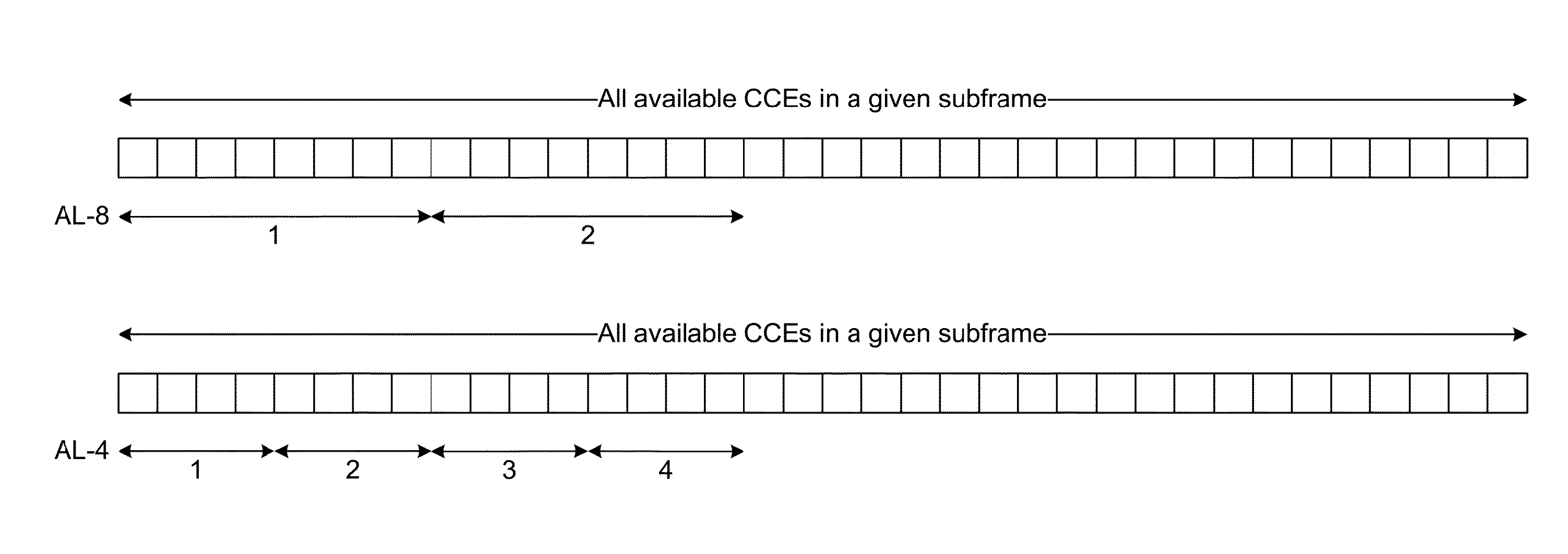
However, the client terminal may not be a priori aware of the AL used by the base station.
This means that at least one false PDCCH is likely to occur every second.
The false PDCCH decoding may lead to false DCI which in turn leads to false resource allocation in the client terminal.
Such false PDCCH detection may cause two types of problems.
If the false PDCCH detection is related to downlink resource allocation then it may cause the client terminal to receive the downlink data that does not actually contain any information for that particular client terminal.
This results in unnecessary power consumption in the client terminal.
Furthermore, if there was another allocation in the same subframe that was actually intended for the client terminal there may be conflict in the allocated resources.
This may cause the client terminal to behave in an unpredictable manner and could result in the client terminal not receiving the data that was intended for it.
For the uplink direction, the false detection of the PDCCH may result in the client terminal transmitting on resources that are not granted to it.
This may cause interference to other client terminal which may be allocated those particular resources.
This may lead to unnecessary power consumption on all the client terminals that may be transmitting on those particular resources.
Furthermore, the bandwidth is wasted in both the downlink and the uplink of the wireless communication system.
False PDCCH detection can also cause the HARQ Finite State Machine (“FSM”) running at the client terminal and at the eNB to be out of sync.
The false PDCCH decoding then in turn leads to transmission of HARQ acknowledgment (positive or negative) in the uplink direction at the wrong location in uplink resources and possibly interfering with other client terminals that may be sending HARQ acknowledgements.
The false PDCCH decoding may lead to a series of problems that compound over a period of few subframes.

Method used


Image

  • Method and apparatus for detecting inconsistent control information in wireless communication systems
  • Method and apparatus for detecting inconsistent control information in wireless communication systems
  • Method and apparatus for detecting inconsistent control information in wireless communication systems

Examples


Embodiment Construction

[0054]Methods and apparatus are described that reduce the probability of false PDCCH detection and duplicate PDCCH detection.

[0055]According to an aspect of the present invention, some false PDCCH detections may be identified by checking the content of the decoded message. The PDCCH carries payloads of different DCI messages. Each of the DCI messages is transmitted according to a specific format comprising a number of bit fields. The output of the PDCCH decoder is parsed for the expected format. In one scenario, the following list of checks is performed for identifying the false PDCCH detection:

[0056]Checks to be Performed to Avoid False PDCCH Before DCI Data Parsing[0057]1. Only one SI-RNTI based PDCCH or P-RNTI based PDCCH may be detected in a subframe.[0058]2. Only one RA-RNTI or C-RNTI or SPS-C RNTI or Temp-C RNTI based PDSCH is allowed in a subframe.[0059]3. Only one PUSCH grant (DCI Format 0) based on C-RNTI, SPS-C RNTI or Temp-C RNTI is allowed in a subframe. For TDD Configur...


PUM


Abstract

In order to support low latency and bursty internet data traffic, the 3GPP LTE wireless communication system uses dynamic allocation. To keep the allocation overhead lower, the system is designed such that the client terminal must perform a number of decoding attempts to detect resource allocations. During course of the decoding attempts a false resource allocation may be decoded by the client terminal. The false detection may lead to multiple issues for the performance efficiency of the client terminal and the overall communication system. A method and apparatus are disclosed than enable the detection of false resource allocation. This in turn improves the performance and efficiency of the client terminal and the wireless communication system.

Description

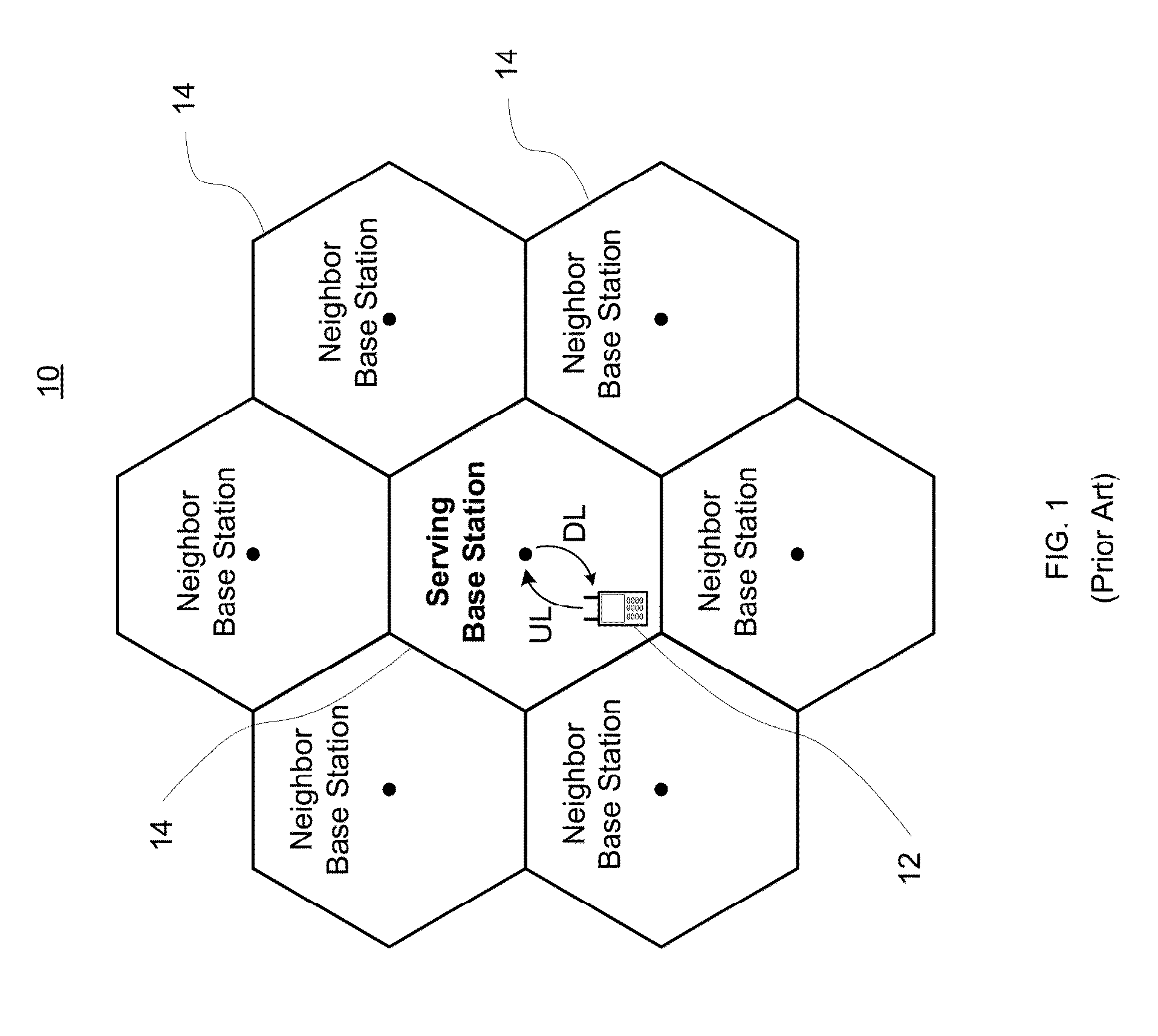
CROSS-REFERENCE TO RELATED APPLICATIONS[0001]This application claims the benefit of the filing date of U.S. Provisional Application No. 61 / 760,167 filed Feb. 4, 2013 and entitled “METHOD AND APPARATUS FOR DETECTING INCONSISTENT CONTROL INFORMATION IN LTE DOWNLINK CONTROL CHANNEL,” the entire disclosure of which is hereby expressly incorporated by reference herein.BACKGROUND OF THE INVENTION[0002]The present invention relates generally to wireless communication systems and, more particularly, to mobile station receiver architectures and methods that employ decoding multiple hypotheses such as in case of 3rd Generation Partnership Project (“3GPP”) Long Term Evolution (“LTE”) wireless communication system.[0003]As shown in FIG. 1, a wireless communication system 10 comprises elements such as a client terminal or mobile station 12 and base stations 14. Other network devices which may be employed, such as a mobile switching center, are not shown. As illustrated, the communication path fr...

Claims


Application Information

Patent Timeline
Patent Type & Authority Applications(United States)
IPC IPC(8): H04L5/00
CPCH04L5/0091H04L1/1812H04L5/0048H04L5/0053
Inventor PATEL, BHASKARGOVINDSWAMY, ARUMUGAM
Owner MBIT WIRELESS
Learn More