
Magnetic resonance system and method to acquire mr data and to determine a b1 magnetic field

a magnetic field and magnetic resonance technology, applied in the field of magnetic resonance system and method to acquire mr data and determine a b1 magnetic field, can solve the problems of disadvantageous adulteration of gradient echo intensity, negative affect or adulteration of mr data acquired for a current sequence, and inability to determine the b1 magnetic field

Inactive Publication Date: 2014-08-07
SIEMENS HEALTHCARE GMBH
View PDF5 Cites 7 Cited by
  • Summary
  • Abstract
  • Description
  • Claims
  • Application Information

AI Technical Summary

Benefits of technology

This patent describes a method for improving magnetic resonance imaging (MRI) data quality by refocusing the echo of a specific magnetization component in each sequence of data readout. This prevents adulteration of the measured data and reduces image artifacts. The method also allows for the determination of the B1 magnetic field for each configuration of transmission channels. Additionally, the method reduces systematic errors and measurement time by achieving a reduction inT1 relaxation between sequences. Overall, this technique improves the accuracy and reliability of MRI data.

Problems solved by technology

A problem can occur that a magnetization prepared in a previous sequence negatively affects or adulterates the MR data acquired for a current sequence.
If such an MR method based on the stimulated echo is used to determine the B1 magnetic field, in particular the intensity of the gradient echo is disadvantageously adulterated (more precisely, increased) due to this problem, such that the determination of the B1 magnetic field is also adulterated.

Method used


Image

  • Magnetic resonance system and method to acquire mr data and to determine a b1 magnetic field
  • Magnetic resonance system and method to acquire mr data and to determine a b1 magnetic field
  • Magnetic resonance system and method to acquire mr data and to determine a b1 magnetic field

Examples


Embodiment Construction

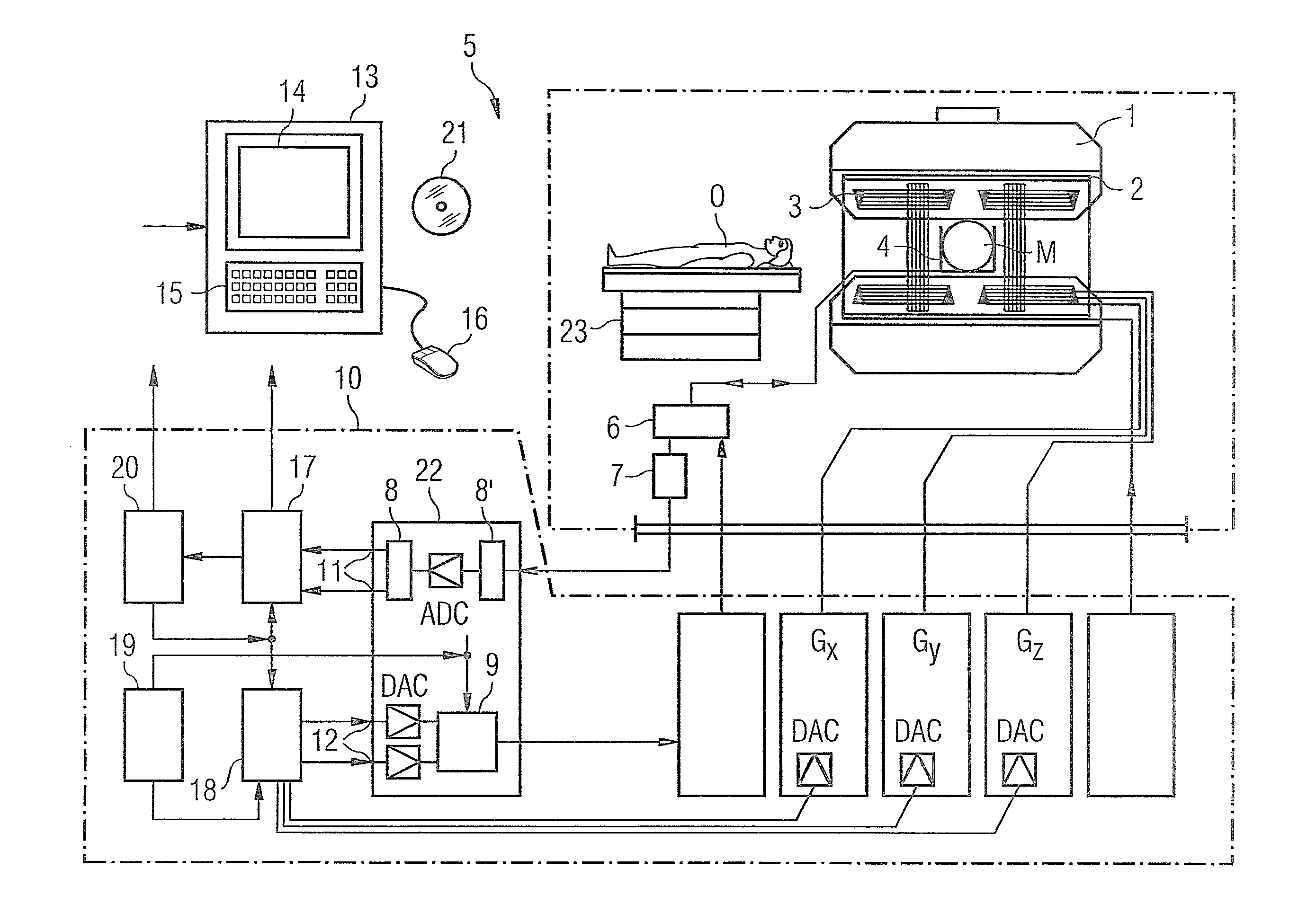
[0062]FIG. 1 is a schematic depiction of a magnetic resonance system 5 (a magnetic resonance or magnetic resonance tomography apparatus). A basic field magnet 1 generates a temporally constant, strong magnetic field for polarization or alignment of the nuclear spins in a volume segment of a subject O (for example of a part of a human body that is to be examined) which, lying on a table 23, is examined in the magnetic resonance system 5. The high homogeneity of the basic magnetic field that is required for the nuclear magnetic resonance measurement is defined in a typically spherical measurement volume M in which the parts of the human body that are to be examined are arranged. To support the homogeneity requirements, and in particular to eliminate temporally invariable influences, what are known as shim plates made of ferromagnetic material are mounted at a suitable location. Temporally variable influences are eliminated by shim coils 2.

[0063]In the basic field magnet 1, a cylindric...


PUM


Abstract

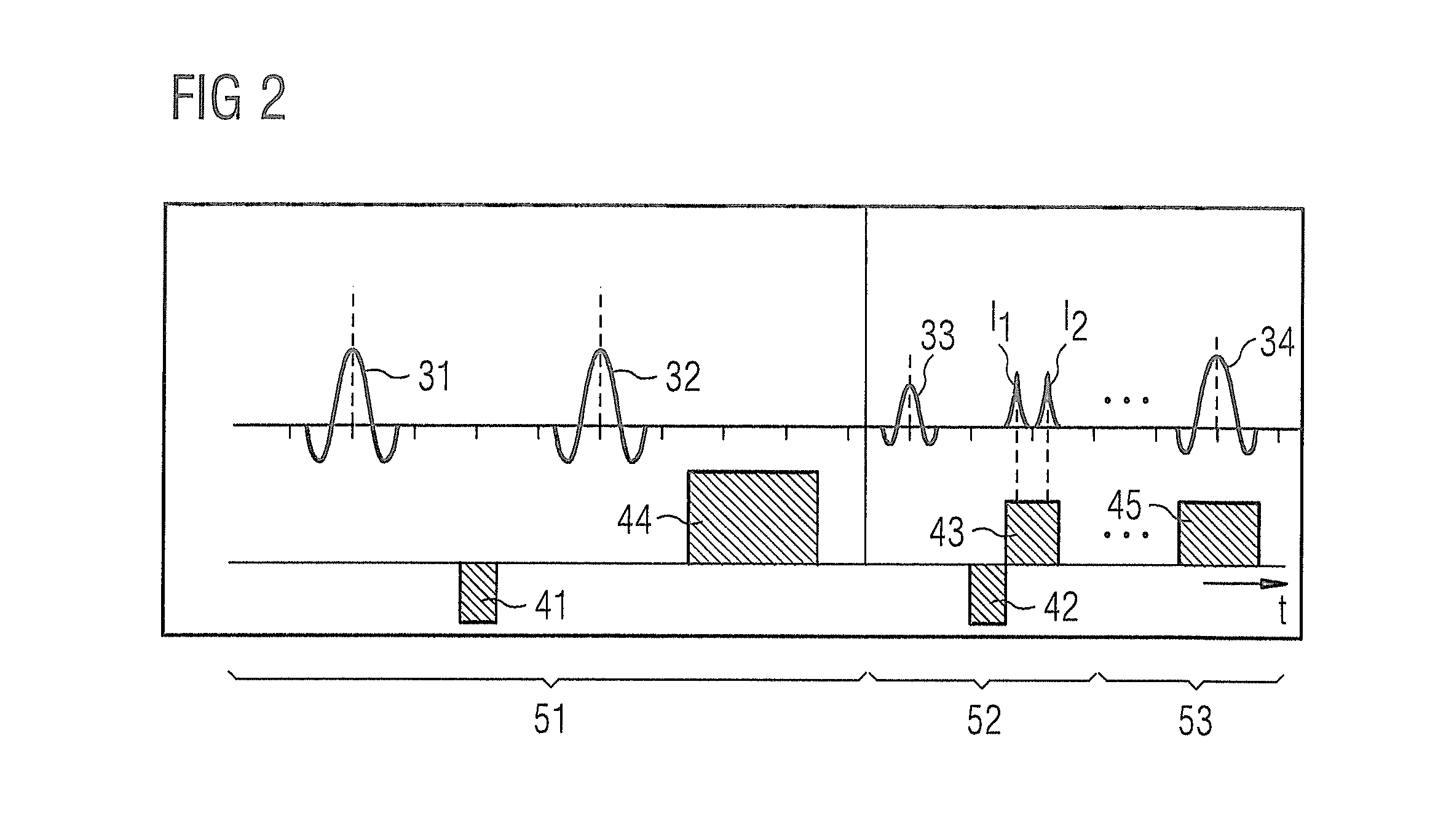
In a method and magnetic resonance (MR) system to acquire MR data within a volume segment, the MR data are repeatedly acquired with a sequence that which includes the following steps. A first resonant RF pulse is radiated and a second resonant RF pulse is radiated. A dephasing first gradient is applied after the first resonant RF pulse and before the second resonant RF pulse. A third resonant RF pulse is radiated after the second resonant RF pulse. A second gradient is applied after the third RF pulse in order to refocus a stimulated echo of a magnetization component prepared by the first gradient. MR data are read out, and a fourth resonant RF pulse is radiated after the readout of the MR data, to reduce the longitudinal magnetization.

Description

BACKGROUND OF THE INVENTION[0001]1. Field of the Invention[0002]The present invention concerns a method in order to acquire magnetic resonance (MR) data (for example to create MR images) and a method in order to determine a B1 magnetic field. Moreover, the present invention concerns a magnetic resonance system that is designed in order to implement one or both of such methods.[0003]2. Description of the Prior Art[0004]Precise knowledge of the B1 magnetic field, which is the strong, static field that is present in the examined region of the examination subject, is of great importance for many applications in the field of magnetic resonance tomography, for example for the calculation of an RF pulse in multichannel transmission operation or for quantitative T1 examinations. In a strong, static B0 magnetic field (for example of a strength of 3 Tesla or more), distinctive spatially dependent variations of the B1 magnetic field can occur due to subject-specific variations in conductivity ...

Claims


Application Information

Patent Timeline
Patent Type & Authority Applications(United States)
IPC IPC(8): G01R33/44G01R33/54
CPCG01R33/54G01R33/443G01R33/246G01R33/34G01R33/44G01R33/483
Inventor KOEHLER, MICHAELSPECKNER, THORSTEN
Owner SIEMENS HEALTHCARE GMBH
Learn More