Machine tool and method for measuring a workpiece

a technology of workpieces and tools, applied in the field of machine tools, can solve the problems of complex design of measuring devices, high cost of linkage development, and high cost of control in operation, and achieve the effect of greater flexibility of measuring devices

Inactive Publication Date: 2014-07-31
FRITZ STUDER AG
View PDF7 Cites 5 Cited by
  • Summary
  • Abstract
  • Description
  • Claims
  • Application Information

AI Technical Summary

Benefits of technology

The machine tool described in this patent is designed to make accurate measurements by combining elements of absolute and relative measurements. This means that any inaccuracies on the machine's side, such as temperature-related deformations, can only affect the measurement result if there is a change in the distance between the two actual positions of the tool unit during probing. The measurement can be done with low error. The calibration or standardization of the measuring device can be easily done using this method. The measuring device with multiple measuring probes is suitable for measuring a variety of workpiece geometries as long as they can be brought into the measurement region.

Problems solved by technology

However, the measuring apparatus has a complex design.
The linkage is developed in a costly manner and is expensive to control in operation.
Expensive setting-up, adjusting or calibrating processes, which are necessary in order to adapt the measuring head for the respective purpose, can be disadvantageous in this case.
This can be disadvantageous in particular in the case of section by section measuring of eccentric workpieces.
The position of the measuring head in relation to the test item, for instance in relation to the angular position thereof, can contain errors.

Method used


Image

  • Machine tool and method for measuring a workpiece
  • Machine tool and method for measuring a workpiece
  • Machine tool and method for measuring a workpiece

Examples


Embodiment Construction

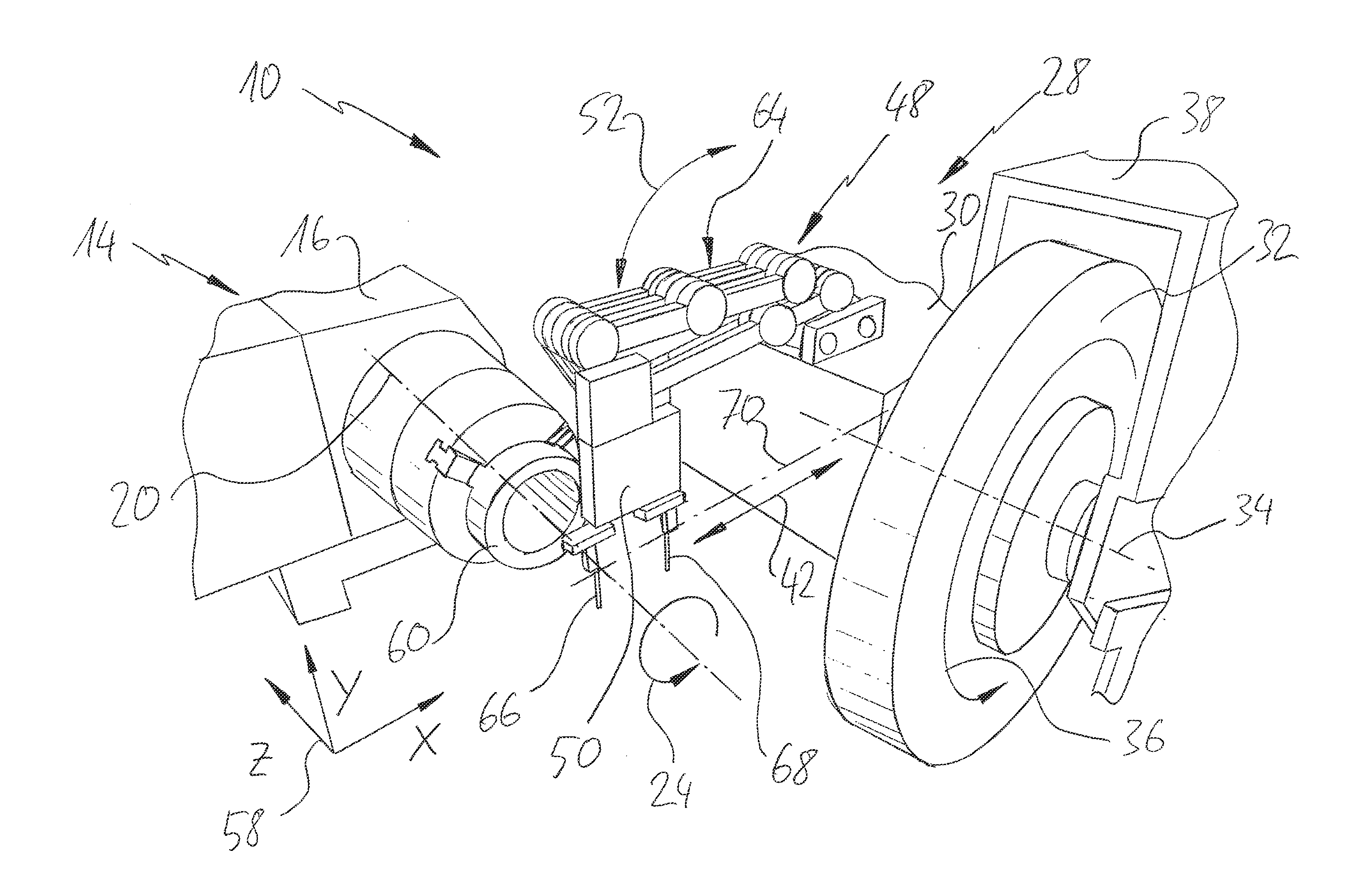
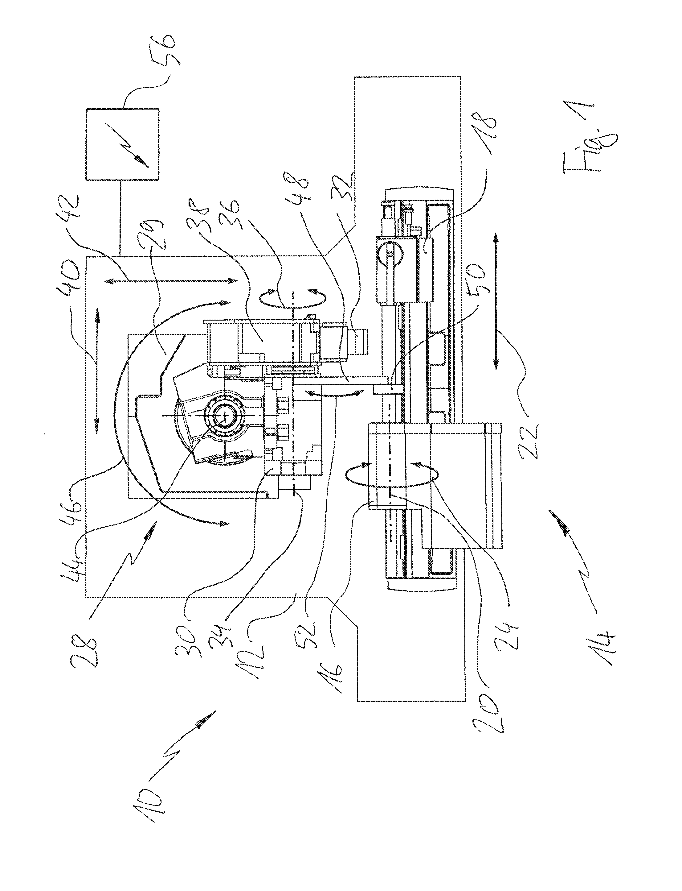
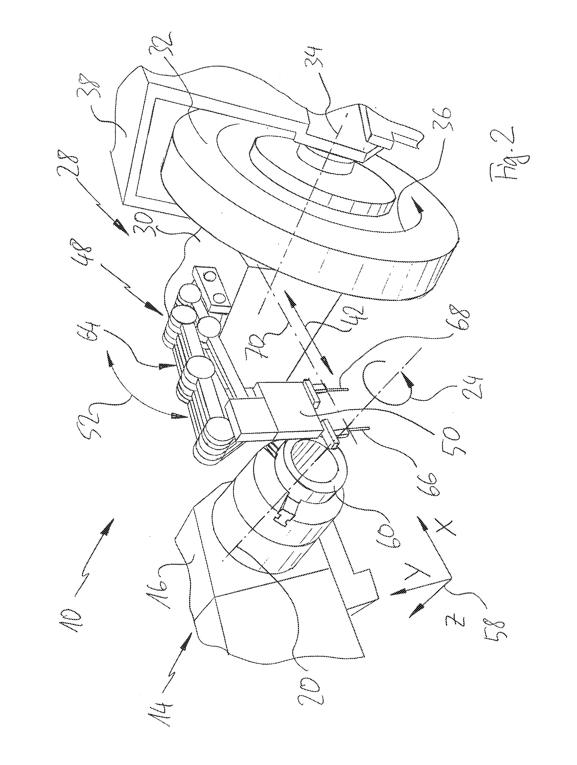
[0091]A machine tool in accordance with the present disclosure is shown in FIG. 1 and is designated overall by the reference 10.

[0092]The machine tool 10 is configured in the present case as a grinding machine. The machine tool 10 comprises a support table 12 which can be arranged, for instance, as part of a framework. A workpiece mount 14 is mounted and guided on the support table 12. The workpiece mount 14 comprises a workpiece spindle headstock which is provided with a workpiece spindle 16. The workpiece spindle 16 comprises a tailstock 18 associated therewith. A workpiece can be mounted between the workpiece spindle 16 and the tailstock 18 (not shown in FIG. 1).

[0093]The workpiece spindle 16 comprises a workpiece spindle axis 20 about which the workpiece is rotationally driveable, where applicable, cf. also an arrow designated by the reference 24. The workpiece spindle axis 20 can also be designated as a C-axis. A C-axis can allow for a targeted, controlled rotation of a workpie...


PUM


Abstract

The present disclosure relates to a machine tool, in particular a grinding machine, and to a method for measuring a workpiece, in particular a workpiece diameter, in a machine tool, in particular a grinding machine, which comprises a workpiece mount, a tool unit, a measuring device and a control device which is connectable to the measuring device and the tool unit, wherein the measuring device is accommodated on the tool unit and comprises at least two measuring probes, wherein in a measuring configuration the at least two measuring probes are spaced apart by a basic spacing which defines a measurement region, wherein the basic spacing is selected to be greater than a known reference dimension, wherein the control device is configured for acquiring values detected by way of the at least two measuring probes, of detecting an actual position of the tool unit, and, on the basis of a displacement path of the tool unit when probing a workpiece which is moved into the measurement region, of determining an actual spacing, in particular an actual diameter, with consideration to the reference dimension and / or the basic spacing.

Description

CROSSREFERENCES TO RELATED APPLICATIONS[0001]This application is a continuation of International Patent Application PCT / EP2012 / 0068947, filed on Sep. 26, 2012 designating the U.S., which international patent application has been published in German language and claims priority from German patent application 10 2011 115 254.0, filed on Sep. 27, 2011. The entire contents of these priority applications are fully incorporated by reference herewith.BACKGROUND OF THE INVENTION[0002]The present disclosure relates to a machine tool, in particular a grinding machine, comprising a workpiece mount, a tool unit, a measuring device and comprising a control device which is connectable to the measuring device and the tool unit. The present disclosure also relates to a method for measuring a workpiece, in particular a workpiece diameter, in a machine tool, in particular a grinding machine.[0003]Machine tools, in particular grinding machines, are known in the prior art. Thus, for example, cylindrica...

Claims


Application Information

Patent Timeline
IPC IPC(8): B24B49/04B23Q17/22B23Q17/20
CPCB24B49/045B23Q17/2233B23Q17/20B24B5/04B24B5/42B24B19/125B24B49/03G01B3/30G01B21/12B24B49/10
Inventor GAEGAUF, FRED
Owner FRITZ STUDER AG
Why Eureka
Try Eureka