Passive system for cooling the core of a nuclear reactor

a passive safety system and nuclear reactor technology, applied in nuclear engineering, nuclear elements, greenhouse gas reduction, etc., can solve the problems of flooding the containment vessel, periodic outages, and the structure of the passive safety system is out of operation

Active Publication Date: 2014-07-24
WESTINGHOUSE ELECTRIC CORP
View PDF10 Cites 6 Cited by
  • Summary
  • Abstract
  • Description
  • Claims
  • Application Information

AI Technical Summary

Benefits of technology

[0017]In accordance herewith, the nuclear power generating facility may also include a passive safety system supported within the containment building approximately at or above a first elevation of the flange and structured to maintain a given level of coolant within the reactor vessel for a first selected period of time, when the coolant level in the reactor vessel unintentionally drops. However, the passive safety system is structured to be out of operation during a refueling of the nuclear core.
[0018]The nuclear power generating facility may also include a refueling canal establishing a fluid communication path between an inside of the containment building at an elevation above the reactor vessel flange and the spent fuel pool, through which a fuel assembly can pass. Means are also provided for isolating the fluid communication path from the inside of the containment. A refueling cavity may also be supported above the reactor vessel flange and the reactor vessel may be fitted with a branch coolant line. Preferably a gauge is provided on the branch coolant line that has an output indicative of the coolant level above the core to control the first valve to adjust the coolant level to a preprogrammed level. In one embodiment, the gauge is a pressure gauge.
[0019]The invention also contemplates a method of passively, safely maintaining the coolant level of the nuclear power generating facility described heretofore, above the nuclear core for an extended period of time during a facility outage in which the reactor vessel is substantially depressurized. The method includes the step of sensing a level of coolant above the nuclear core. The method then controls the first valve to drain coolant from the spent fuel pool into the reactor vessel to maintain the coolant within the reactor vessel at a preprogrammed level above the nuclear core. The method also controls the second valve to drain coolant from the ultimate heat sink coolant reservoir into the spent fuel pool to maintain the coolant in the spent fuel pool at approximately the preselected level. In the foregoing embodiment, in which the nuclear power generating facility h

Problems solved by technology

Nuclear power plants, which employ light water reactors require periodic outages for refueling of the reactor.
However, the passive safety system is structured to be out of operation during a refueli

Method used


Image

  • Passive system for cooling the core of a nuclear reactor
  • Passive system for cooling the core of a nuclear reactor
  • Passive system for cooling the core of a nuclear reactor

Examples


Embodiment Construction

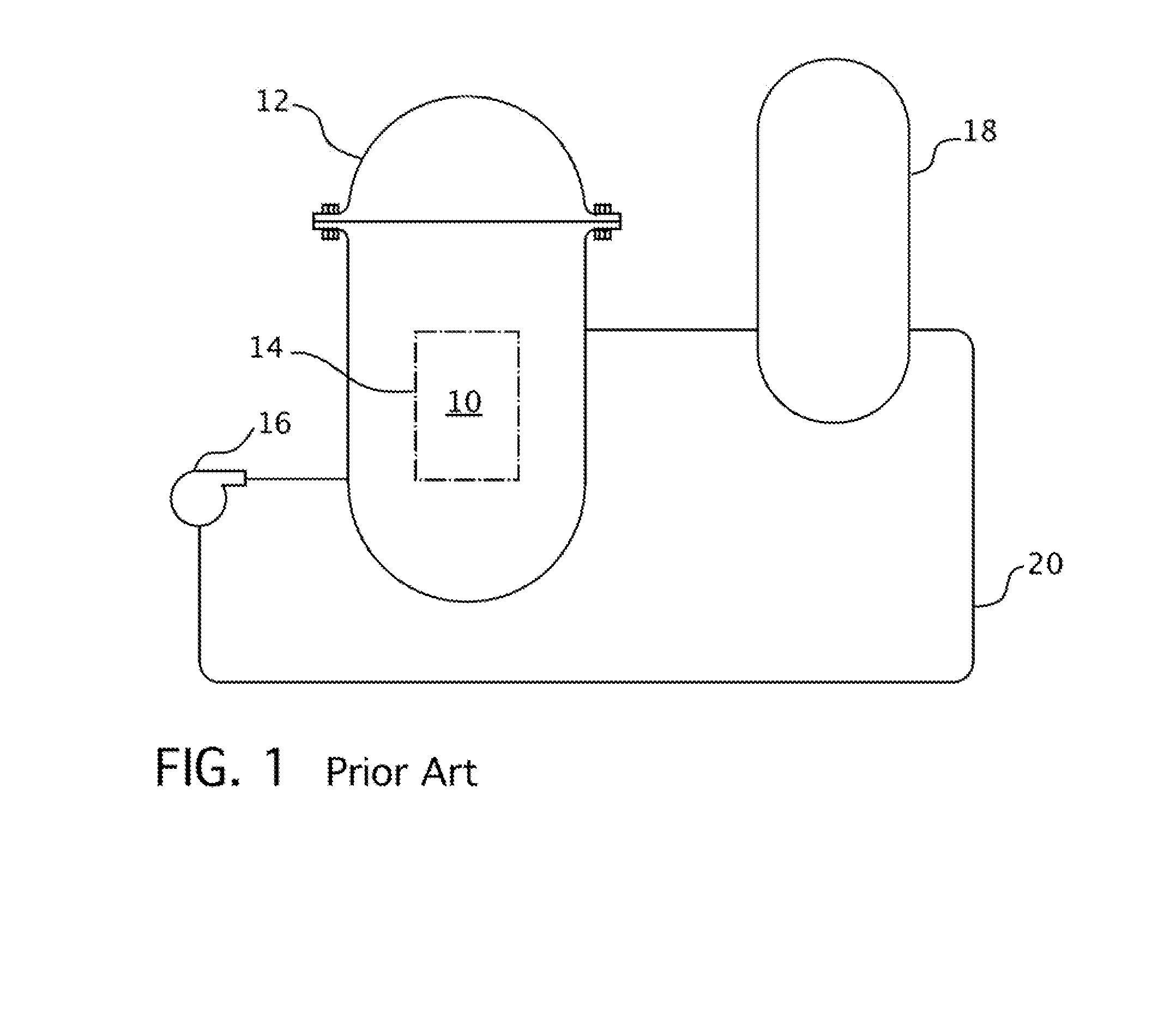
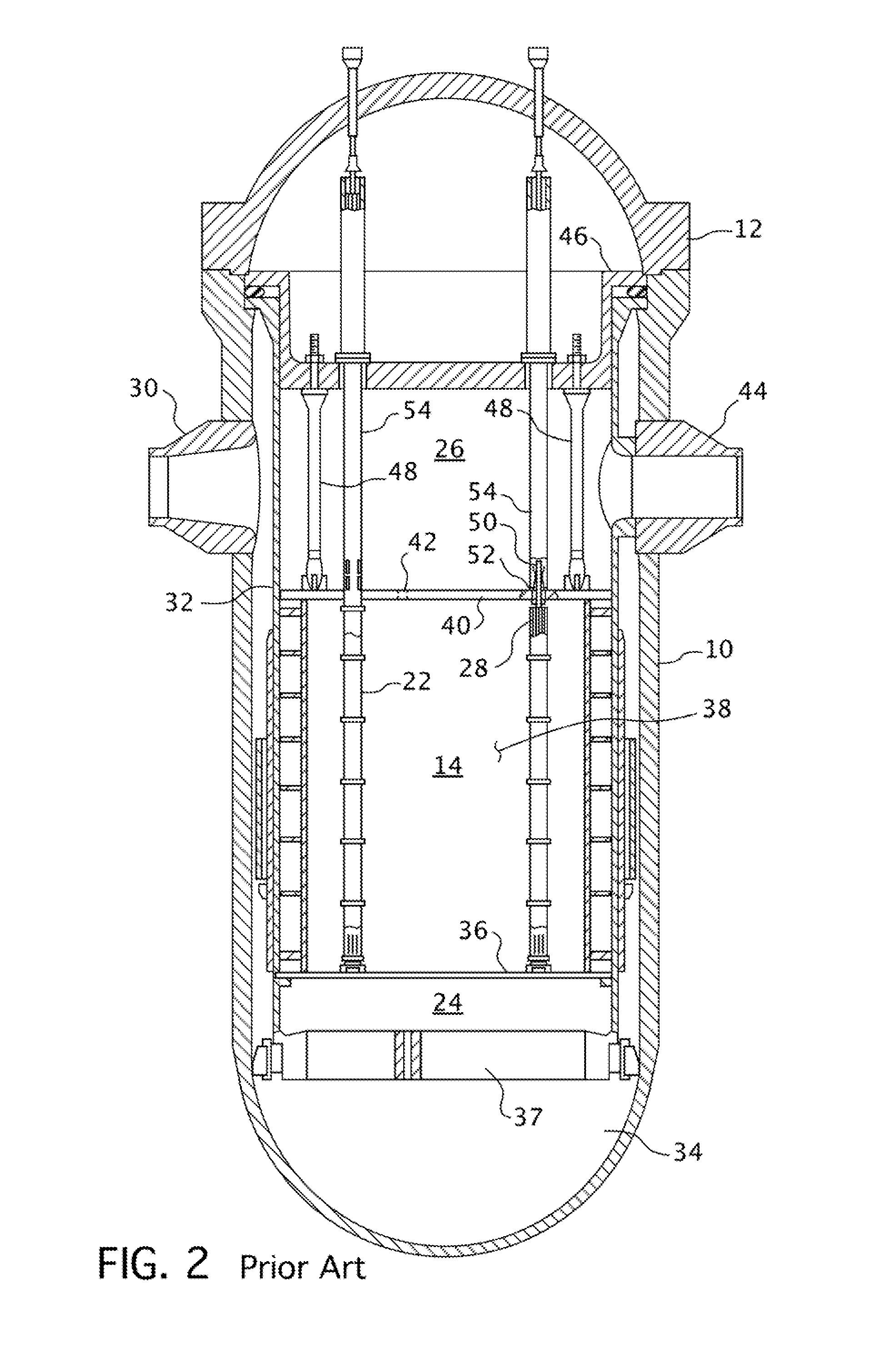
[0034]FIGS. 3 and 4 illustrate a small modular reactor design available from Westinghouse Electric Company LLC, Cranberry Township, Pennsylvania, to which this invention may be applied, though it should be appreciated that the invention can also be applied to a conventional pressurized water reactor such as the one illustrated in FIGS. 1 and 2. FIG. 3 shows a perspective view of the reactor containment 11, partially cut away, to show the pressure vessel 10 and its internal components. FIG. 4 is an enlarged view of the pressure vessel shown in FIG. 3. The pressurizer 58 is common to most pressurized water reactor designs, though not shown in FIG. 1, and is typically included in one loop to maintain the systems' pressure. In the small modular reactor design illustrated in FIGS. 3 and 4, the pressurizer 58 is integrated into the upper portion of the reactor vessel head 12 and eliminates the need for a separate component. It should be appreciated that the same reference characters are e...


PUM


Abstract

A system for passively cooling nuclear fuel in a pressurized water reactor during refueling that employs gravity and alignment of valves using battery reserves or fail in a safe position configurations to maintain the water above the reactor core during reactor disassembly and refueling. A large reserve of water is maintained above the elevation of and in fluid communication with the spent fuel pool and is used to remove decay heat from the reactor core after the reaction within the core has been successfully stopped. Decay heat is removed by boiling this large reserve of water, which will enable the plant to maintain a safe shutdown condition without outside support for many days.

Description

CROSS REFERENCE TO RELATED APPLICATIONS[0001]This application is related to U.S. patent application Ser. No. 13 / 495,083, filed Jun. 13, 2012, entitled “Small Modular Reactor Safety Systems,” (Attorney Docket No. RTU 2011-011).BACKGROUND[0002]1. Field[0003]This invention pertains generally to nuclear reactor safety systems, and more particularly, to a system for passively cooling the core of a nuclear reactor and a spent fuel pool during a refueling outage in the event of a nuclear station blackout.[0004]2. Description of Related Art[0005]A pressurized water reactor has a large number of elongated fuel assemblies mounted within an upright reactor vessel. Pressurized coolant is circulated through the fuel assemblies to absorb heat generated by nuclear reactions in fissionable material contained in the fuel assemblies. The primary side of such a nuclear reactor power generating system which is cooled with water under pressure comprises an enclosed circuit which is isolated from and in ...

Claims


Application Information

Patent Timeline
IPC IPC(8): G21C15/18
CPCG21C15/18G21D3/06G21C19/07Y02E30/00Y02E30/30
Inventor HARKNESS, ALEXANDER W.
Owner WESTINGHOUSE ELECTRIC CORP
Why Eureka
Try Eureka