Amtec unit cell with partially opened internal electrode and method for manufacturing the amtec cell

a technology of amtec and internal electrode, which is applied in the manufacture/treatment of thermoelectric devices, electrolytic capacitors, and temperature-sensitive devices, etc. it can solve the problems of high temperature, high amtec work difficulty, and large internal electricity collection difficulty, so as to overcome the difficulty of electricity collection and easy to collect electricity. , the effect of fine structur

Active Publication Date: 2014-07-24
KOREA INST OF ENERGY RES
View PDF4 Cites 2 Cited by
  • Summary
  • Abstract
  • Description
  • Claims
  • Application Information

AI Technical Summary

Benefits of technology

The present invention provides an open internal electrode AMTEC unit cell with a metal support and a thin film solid electrolyte layer. A metal filler is used to seal the pores in the curved portion of the internal electrode, and an external electrode is coated on the solid electrolyte layer. The cell has durability at high temperatures and pressures, and the efficiency is improved by the dense fine structure. The main technical effects of this invention are as follow: easy collection of electricity, avoidance of wire short and electrical loss, simplification of assembly process, and improved efficiency.

Problems solved by technology

However, the NASICON has a problem in its stability of crystal structure when it is exposed to high temperature for a long time.
The AMTEC works at a high temperature and is very corrosive.
Also, the AMTEC has various junctions with the shape of tube so that it has a great difficulty in internally collecting electricity.
It is difficult not only to collect electricity within the cell without interface loss but also to outward pull a lead wire after collecting the electricity.
Particularly, in a general structure of the AMTEC module, since the lower portion of the AMTEC module is formed as a high temperature portion, there is a difficulty.
The junction is required to be electrically insulated, so that it is also difficult to pull the lead wire into the penetration surface of a tube of which one end is open.

Method used


Image

  • Amtec unit cell with partially opened internal electrode and method for manufacturing the amtec cell
  • Amtec unit cell with partially opened internal electrode and method for manufacturing the amtec cell
  • Amtec unit cell with partially opened internal electrode and method for manufacturing the amtec cell

Examples


Embodiment Construction

[0020]An open internal electrode AMTEC unit cell according to the present invention, a manufacturing method thereof and an embodiment of a method for connecting circuits will be described with reference to the accompanying drawings.

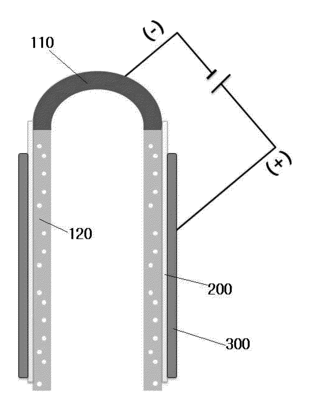
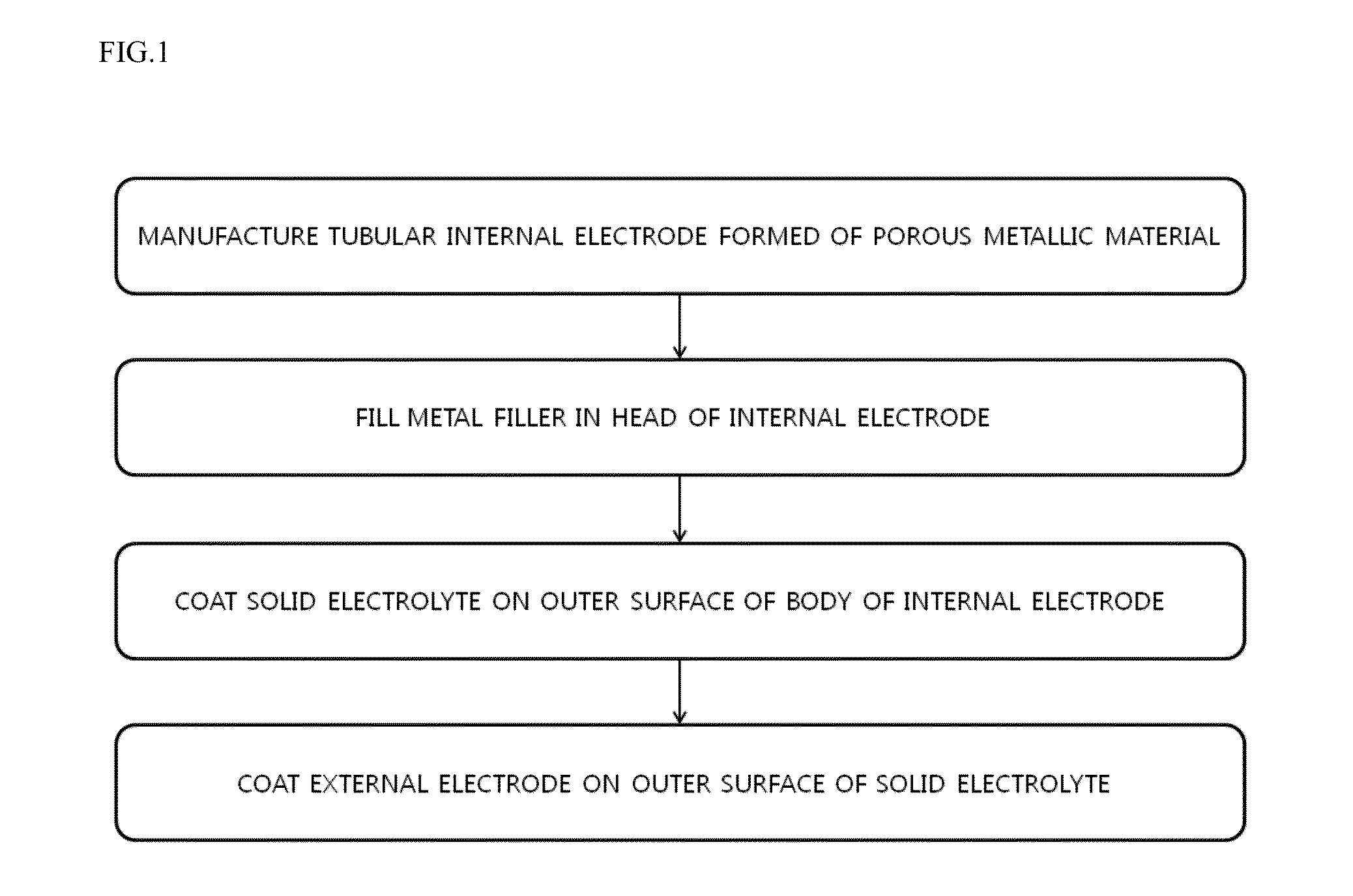
[0021]FIG. 1 is a flowchart showing, step-by-step, a method for manufacturing an open internal electrode AMTEC unit cell of the present invention. The method for manufacturing the AMTEC unit cell includes: manufacturing a tubular internal electrode 100 including a head 110 which is formed of a porous metallic material and has any one of a hemispherical shape, a semi-elliptical shape and a cylindrical shape having one open side, and a cylindrical body 120 which has both open sides; filling a metal filler in order to seal the pores in the head 110; coating the solid electrolyte 200 on the outer surface of the body 120; and coating an external electrode 300 on the outer surface of the coated portion of the solid electrolyte 200.

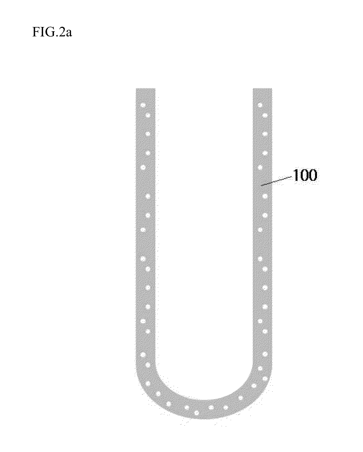
[0022]FIG. 2a is a view showin...


PUM

PropertyMeasurementUnit
Shapeaaaaaaaaaa
Electrical conductoraaaaaaaaaa

Abstract

Disclosed are an open internal electrode AMTEC unit cell, a method for manufacturing the same and a method for connecting circuits. In order to overcome the difficulty in collecting electricity within a conventional AMTEC unit cell, an internal electrode of which a portion is open to the outside, so that the internal electrode and an external electrode can be electrically connected to each other at the outside of the unit cell, and a metal support is used as the internal electrode, so that the internal electrode has durability and stability, and a solid electrolyte is formed in the form of a thin film, and as a result, the AMTEC unit cell has an improved efficiency and a simpler manufacturing process.

Description

CROSS REFERENCE TO PRIOR APPLICATIONS[0001]This application claims priority under 35 U.S.C. §119 to Korean Patent Application No. 10-2013-0007046, filed on Jan. 22, 2013, which is hereby incorporated by reference in its entirety.BACKGROUND[0002]1. Field[0003]The present invention relates to an alkali metal thermal to electric converter (AMTEC) unit cell, and more particularly to an open internal electrode AMTEC unit cell which has an internal electrode of which a portion is open to the outside and thus is capable of connecting the internal electrode to an external electrode at the outside thereof, without directly collecting electricity within the AMTEC unit cell, a method for manufacturing the AMTEC unit cell and an electrically connecting method in the AMTEC unit cell.[0004]2. Description of Related Art[0005]The development of alkali metal thermal to electric converter (AMTEC) technology has started for the purpose of a power source for space. The AMTEC has a high power density pe...

Claims


Application Information

Patent Timeline
IPC IPC(8): H01G9/21H01G9/00
CPCH01G9/21H01G9/0036H01G9/0029H10N10/17H10N10/01
Inventor KIM, SUN-DONGKIM, SE-YOUNGWOO, SANG-KUKJOO, JONG-HOONHAN, IN-SUBSEO, DOO-WONSUH, MIN-SOO
Owner KOREA INST OF ENERGY RES
Why Eureka
Try Eureka