Worktable sliding block positioning mechanism

a positioning mechanism and worktable technology, applied in mechanical devices, manufacturing tools, gearing, etc., can solve the problems of shortening the life of sliding rails and sliding blocks, and the design of sliding block positioning mechanisms is still not satisfactory in function, so as to prevent deformation or displacement of sliding blocks

Inactive Publication Date: 2014-07-24
CARPENTER MACHINERY
View PDF8 Cites 3 Cited by
  • Summary
  • Abstract
  • Description
  • Claims
  • Application Information

AI Technical Summary

Benefits of technology

[0006]The present invention has been accomplished under the circumstances in view. It is the main object of the present invention to provide a worktable sliding block positioning mechanism, which prevents deformation or displacement of the sliding block due to the effect of an external force during its positioning.

Problems solved by technology

However, this design of sliding block positioning mechanism is still not satisfactory in function.
Further, the sliding rail can easily be damaged by the tightening-up screw, leading to unsmooth operation between the sliding rail and the sliding block and shortening the lifespan of the sliding rail and the sliding block.

Method used


Image

  • Worktable sliding block positioning mechanism
  • Worktable sliding block positioning mechanism
  • Worktable sliding block positioning mechanism

Examples


Embodiment Construction

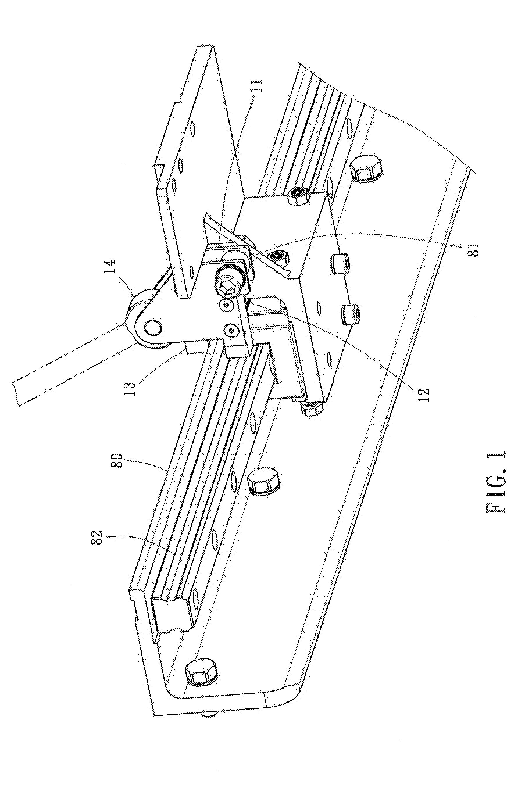
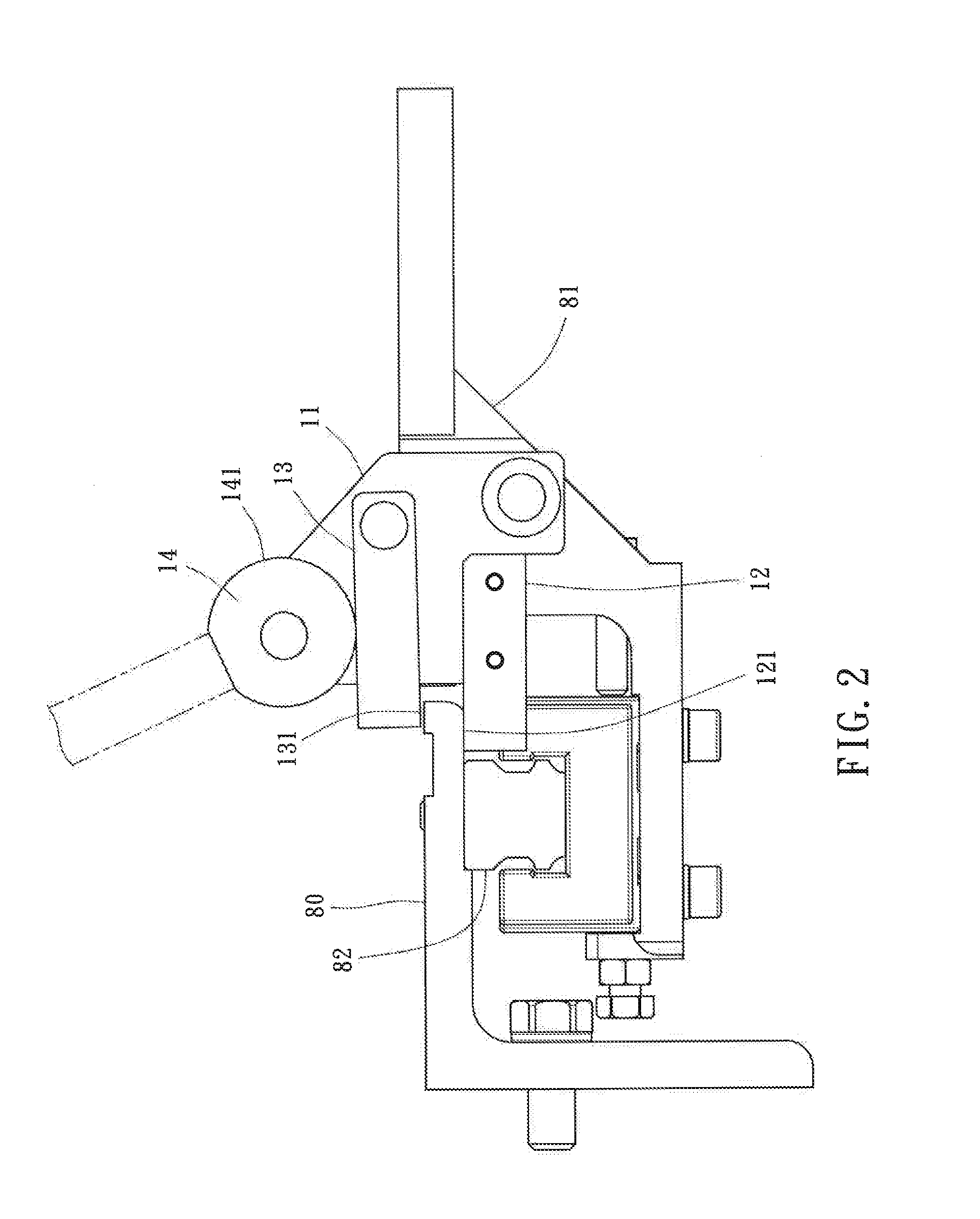
[0015]Referring to FIGS. 1-3, a worktable sliding block positioning mechanism in accordance with a first embodiment of the present invention is shown pivotally coupled to a sliding block 81 that is movable along a fixed sliding rail 82 of a worktable80. The worktable sliding block positioning mechanism comprises a base member 11, a first clamping block 12, a second clamping block 13, and a drive wheel 14.

[0016]The base member 11 in this embodiment is a plate member pivotally coupled to the sliding block 81.

[0017]The first clamping block 12 is fixedly connected to the base member 11, defining a first clamping end 121. The first clamping end 121 is disposed at one side relative to the worktable 80. In this embodiment, the first clamping end 121 is disposed at an outer side relative to the bottom wall of the worktable 80.

[0018]The second clamping block 13 is pivotally connected to the base member 11, defining a second clamping end 131. The second clamping block 13 is disposed at one si...


PUM


Abstract

A worktable sliding block positioning mechanism includes abuse member pivotally connected to a sliding block, a first clamping block affixed to the base member and defining a first clamping end that is disposed at one side relative to the worktable, a second clamping block pivotally connected to the base member and defining a second clamping end that is disposed at an opposite side relative to the worktable and opposite to the first clamping end, and a drive wheel pivotally connected to the base member and rotatable by an external force and defining a press portion that is pressed on the second clamping block to move the second clamping end toward the first clamping end of the first clamping block upon a rotary motion of the drive wheel. Thus, the worktable sliding block positioning mechanism avoids deformation or displacement of the sliding block during its positioning.

Description

BACKGROUND OF THE INVENTION[0001]1. Field of the Invention[0002]The present invention relates to positioning technology and more particularly, to a worktable sliding block positioning mechanism.[0003]2. Description of the Related Art[0004]A machinery equipment generally provides a worktable for holding a workpiece for processing. During processing, the worktable works as a reference surface. Further, the worktable may be equipped with a sliding block to facilitate accurate movement of the workpiece on the worktable, and a sliding block positioning mechanism for locking the sliding block to the worktable. Linking between the aforesaid sliding block and worktable is achieved by means of a sliding rail. The sliding rail is affixed to the worktable. The sliding block is movable along the sliding rail. The sliding block positioning mechanism is affixed to the sliding block and movable along the sliding rail relative to the worktable.[0005]A sliding block positioning mechanism is known co...

Claims


Application Information

Patent Timeline
Patent Type & Authority Applications(United States)
IPC IPC(8): B23Q1/44
CPCB23Q1/44B23Q1/28B25H1/0057B25H1/10Y10T74/18288
Inventor CHANG, CHIN-HSUEH
Owner CARPENTER MACHINERY
Why Eureka
Try Eureka