
Liquid pump

a technology of centrifugal pump and liquid pump, which is applied in the direction of liquid fuel engine, machine/engine, stators, etc., can solve the problems of reducing the efficiency of the pump, affecting the sealing effect of the seal, and affecting the sealing effect, so as to prolong the life, and prevent damage to the seal

Active Publication Date: 2014-07-17
LIBERTY PUMPS
View PDF6 Cites 18 Cited by
  • Summary
  • Abstract
  • Description
  • Claims
  • Application Information

AI Technical Summary

Benefits of technology

The patent text describes a liquid pump with a unique design that reduces manufacturing and assembly costs while improving precision. The pump includes a unitary pump volute with certain features such as a cylindrical cavity, a first annular structure, a second annular structure, and a planar flange. The pump also has a motor housing that is connected to the pump volute. The pump includes a seal that prevents fluid leakage and a cutting assembly that reduces friction and drag in the liquid to be pumped, resulting in increased efficiency and reduced energy consumption.

Problems solved by technology

Under normal operation, the slurry passes through the impeller vanes and volute casing without problems; however problems often do occur.
Solid debris from the slurry often accumulates between the vanes of the impeller and the stationary volute casing, causing undesired friction and load on the pump motor, which reduces the efficiency of the pump.
In the worst cases, the debris may block an entire vane passageway or jam the impeller.
These record grooves are of limited effectiveness, particularly with certain types of solid materials in the slurry.
In either case, the seal is damaged.
In a related aspect, a pump may be damaged if it is run dry, even if for only a short period of time.
In particular, the seal may be damaged by running the pump without having adequate liquid in the volute to maintain the seal in a wet condition.
The cost of energy is becoming an increasingly important consideration when selecting a pump for a given application.
The basic structure of a centrifugal grinder pump has remained quite complex, in that the pump includes a pump motor housing, a multi-piece pump volute, and a grinding device, which are expensive to manufacture individually, and to assemble in a reliable manner.

Method used


Image

  • Liquid pump
  • Liquid pump
  • Liquid pump

Examples


Embodiment Construction

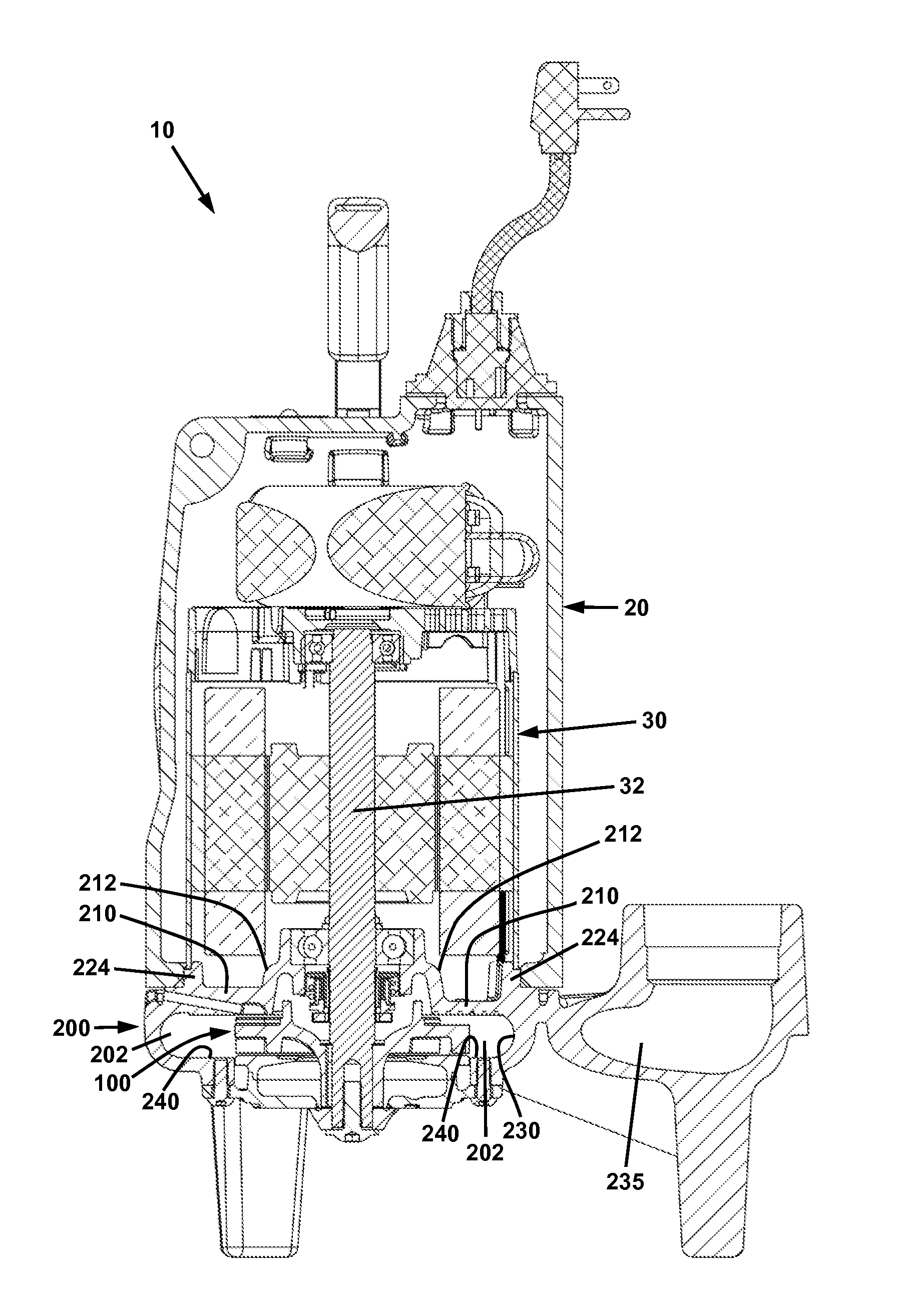
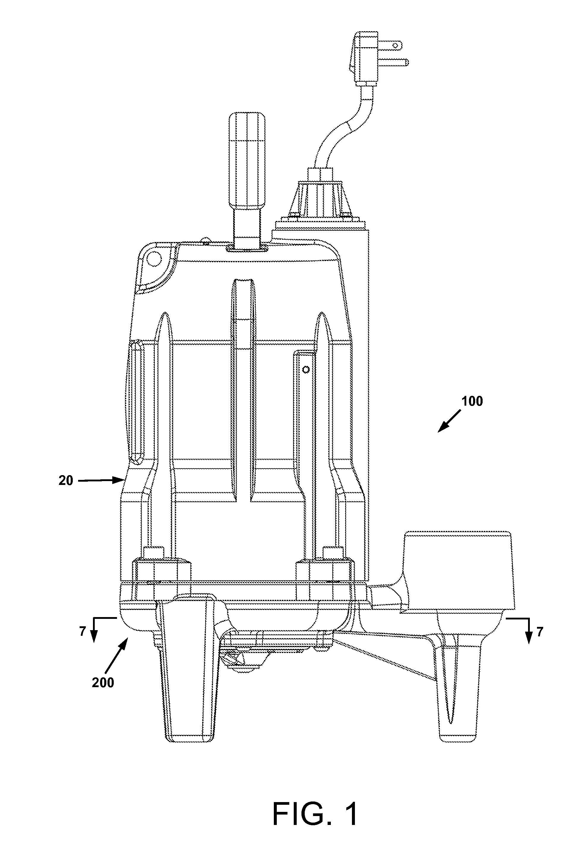
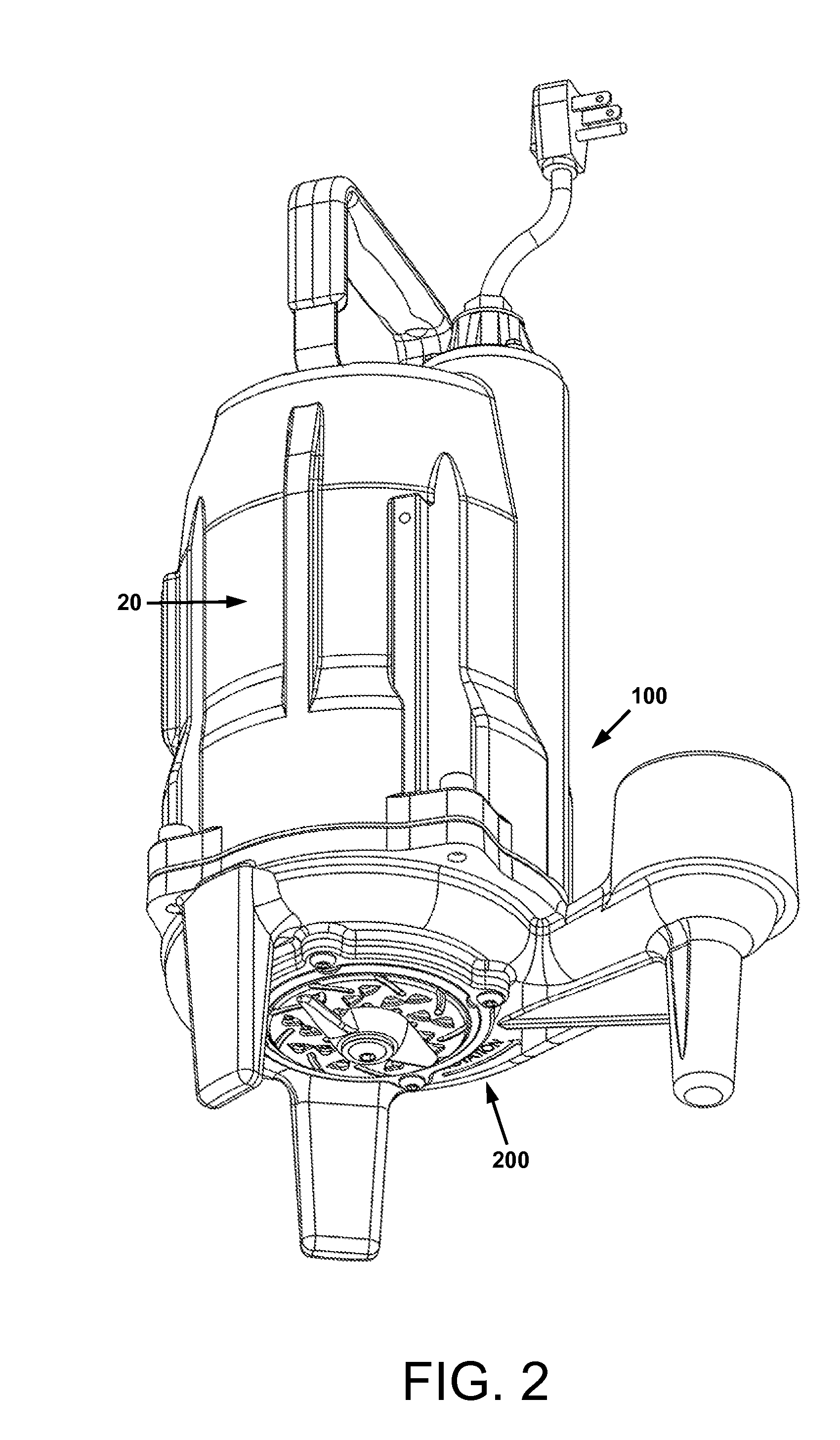
[0040]For a general understanding of the present invention, reference is made to the drawings. In the drawings, like reference numerals have been used throughout to designate identical elements. In the following disclosure, certain components of the invention may be identified with adjectives such as “top,”“upper,”“bottom,”“lower,”“left,”“right,” etc. These adjectives are provided in the context of use of the Applicants' pumps in a position in which the axis of pump impeller rotation is vertical, and / or in the context of the orientation of the drawings, which is arbitrary. The description is not to be construed as limiting the Applicants' pumps to use in a particular spatial orientation. The instant pumps may be used in orientations other than those shown and described herein.

[0041]Additionally, certain embodiments of the Applicants pumps are described with the drawings showing a “grinder pump,” i.e., a pump that is used to macerate solids entrained in the liquid to be pumped. It is...


PUM


Abstract

A pump for pumping liquids containing entrained solids. The pump is comprised of a volute surrounding an impeller comprising vanes that are self-cleaning. The outer surfaces of the vanes are coplanar and define a first plane and have a leading edge. The volute is comprised of a planar mating surface defining a second plane parallel to the first plane of the rotary impeller. The planar mating surface is proximate to the outer surfaces of the vanes and is comprised of a plurality of channels extending radially from the inner perimeter to the outer perimeter thereof. Each channel includes a forward edge in the direction of impeller rotation. The channels are oriented such that when the impeller is rotated within the volute, for any vane, the leading edge of the vane traverses each channel progressively from the inner end of the channel to the outer end of the channel.

Description

BACKGROUND[0001]1. Technical Field[0002]Pumps for the transfer of liquids; more particularly, centrifugal pumps, and centrifugal grinding pumps.[0003]2. Description of Related Art[0004]A pump is a device used to transport liquid from a lower to a higher elevation, or from a vessel of lower pressure to a vessel of higher pressure, or to a state of low velocity to a state of high velocity. Generally, in transporting a liquid, a pump adds energy to the liquid. Typically, an electric motor or other suitable motor is used to spin an impeller or other liquid driver inside a volute casing, transferring energy to the liquid. In many instances, a pump is submerged in a pool and its discharge is connected to a pipe that is used to convey the liquid to a higher elevation. Although pumps have been known for millennia, and advances in the design and manufacturing of pumps have continued right up to the present, there remain opportunities for improvement in many aspects of pump design, such as ef...

Claims


Application Information

Patent Timeline
IPC IPC(8): F04D1/00
CPCF04D1/00F04D7/045F04D29/167F04D29/426F04D29/628
Inventor POHLER, DONALD M.
Owner LIBERTY PUMPS
Learn More