
Systems and Methods for Energy Efficient Machine Condition Monitoring of Fans, Motors, Pumps, Compressors and Other Equipment

a technology of machine condition monitoring and energy-saving monitoring, applied in the direction of instruments, nuclear elements, high-level techniques, etc., can solve the problems of processing system backup, machine failure, and significant financial losses, and achieve the effect of reducing power consumption, reducing power consumption, and saving power

Active Publication Date: 2014-07-10
AB SKF
View PDF2 Cites 10 Cited by
  • Summary
  • Abstract
  • Description
  • Claims
  • Application Information

AI Technical Summary

Benefits of technology

The present invention aims to reduce power consumption while monitoring machine conditions. This may include reducing power consumption during data acquisition, processing, and transmission. Additionally, the invention seeks to increase the battery life of sensors and receivers used for machine condition monitoring. Furthermore, data compression programs and systems are applied to increase the efficiency of data sharing and processing during machine condition monitoring.

Problems solved by technology

Despite increasingly efficient maintenance programs, at any time some percentage of the machines develop defects that are likely to lead to machine failure.
For example, machines having moving parts (e.g., bearings) and experience constant friction that results in wear.
It is known that bearing failures are a major cause of motor faults.
Bearing damage due to wear may not be apparent absent gross damage or failure of the motor, however, because the bearing's wear site is likely concealed in the motor's assembled state.
Unscheduled plant shutdowns can result in considerable financial losses.
Failure of high performance machinery can lead to fatal injury and processing system backup.
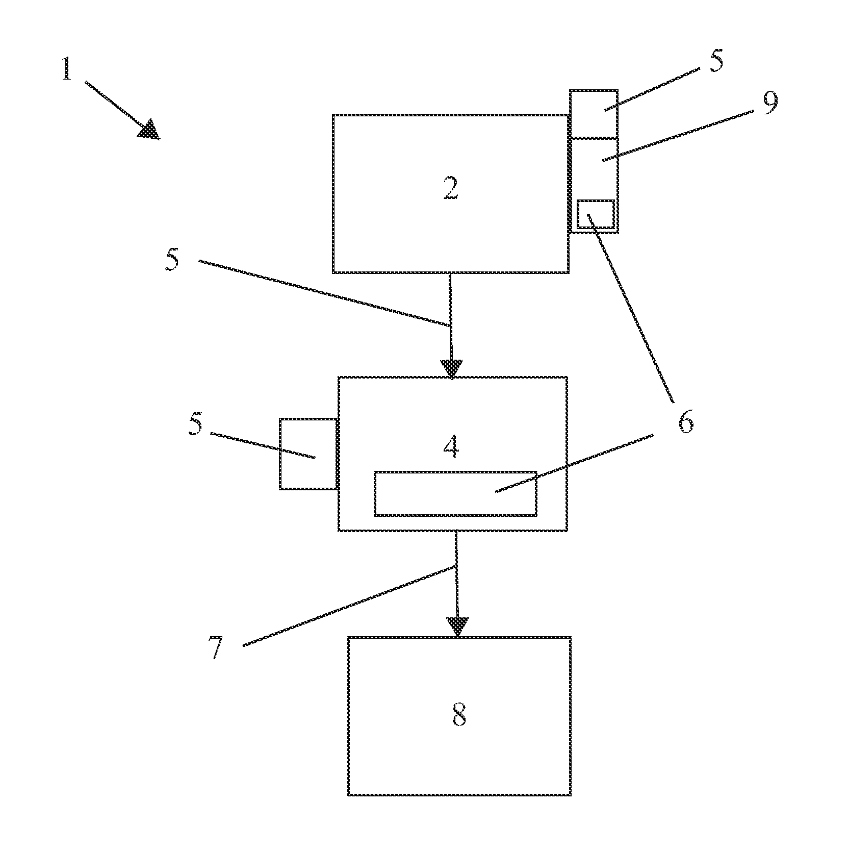
The hand-held unit or other wireless vibration sensors may be battery powered and may consume substantial power during the acquisition, transmission, and processing steps.
The transmission step may consume the most power.

Method used


Image

  • Systems and Methods for Energy Efficient Machine Condition Monitoring of Fans, Motors, Pumps, Compressors and Other Equipment
  • Systems and Methods for Energy Efficient Machine Condition Monitoring of Fans, Motors, Pumps, Compressors and Other Equipment
  • Systems and Methods for Energy Efficient Machine Condition Monitoring of Fans, Motors, Pumps, Compressors and Other Equipment

Examples


Embodiment Construction

[0022]The present invention includes a variety of aspects, which may be combined in different ways. The following descriptions are provided to list elements and describe some of the embodiments of the present invention. These elements are listed with initial embodiments, however it should be understood that they may be combined in any manner and in any number to create additional embodiments. The variously described examples and preferred embodiments should not be construed to limit the present invention to only the explicitly described systems, techniques, and applications. Further, this description should be understood to support and encompass descriptions and claims of all the various embodiments, systems, techniques, methods, devices, and applications with any number of the disclosed elements, with each element alone, and also with any and all various permutations and combinations of all elements in this or any subsequent application.

[0023]In general, the present invention may p...


PUM


Abstract

Methods and systems to achieve highly efficient rotational machine integrity determinations in which at least one sensor (106) senses indicia (105) such as time-varying rotational indicia from a rotational motive apparatus (103) and a processor (108) may provide many different functions including but not limited to operational function energy apportioning decisional processing, data compression, intelligent hierarchical data ranking, differential data processing, or the like perhaps to generate information (109) such as a rotational integrity abridgment transmissor to which an abridgment transmissor electromagnetic signal (112) may be created and perhaps even transmitted from a rotational motive apparatus to facilitate a machine integrity determination.

Description

PRIORITY CLAIM[0001]This application is an international PCT application claiming the benefit of and priority to U.S. Provisional Application No. 61 / 582,278 filed Dec. 31, 2011, hereby incorporated by reference herein.TECHNICAL FIELD[0002]The present invention generally relates to systems and methods for energy efficient monitoring of machine conditions. More particularly, the present invention concerns systems and methods for energy efficient data processing and even transmission in machine condition monitoring systems including but not limited to monitoring systems for electrical motors, rotational machines, non-rotational machines, and the like.BACKGROUND[0003]It is common for industrial and commercial facilities to operate a large number of machines such as electrical motors concurrently, many of which may cooperate in a large interdependent process or system. Despite increasingly efficient maintenance programs, at any time some percentage of the machines develop defects that ar...

Claims


Application Information

Patent Timeline
Patent Type & Authority Applications(United States)
IPC IPC(8): G01M99/00
CPCG01M99/005G01H1/003G01M7/00G01M13/00G01M13/028H04W52/0261Y02D30/70G08C2201/12
Inventor BOERHOUT, JOHANNES I.
Owner AB SKF
Learn More