Network power control module

a network power control and multi-functional technology, applied in the field of remote control equipment, can solve the problems of limited practicality, reduced user willingness to use, and limited remote control using distan

Active Publication Date: 2014-07-10
WU LAI FU
View PDF11 Cites 8 Cited by
  • Summary
  • Abstract
  • Description
  • Claims
  • Application Information

AI Technical Summary

Benefits of technology

The present invention provides a network power control module that allows users to remotely control indoor electronic devices at home or in office. This improves security, convenience, and comfortability of the living and working environments. The communication module has a wireless access point function and supports wireless expansion in the area. The module has a group list to connect multiple electronic devices and automatically control their operating status. The module also includes an AC / DC converter and a power switch to improve power supply stability. The invention uses a router to centralize management of electronic devices and facilitate user scheduling management.

Problems solved by technology

However, the remote control has a limited using distance, and the universal remote control has the drawbacks of complicated setup and little control functions, and thus the practicality is limited.
There are various models and manufacturers of the information appliances, so that if each management program just allows its use for a particular model of the electric appliance or a particular manufacturer, a complicated pre-installation operation will be required, and these programs are unfavorable for management and use, so that the users' willingness of use will be reduced, and the consumer satisfaction will be lowered.

Method used


Image

  • Network power control module
  • Network power control module
  • Network power control module

Examples


Embodiment Construction

[0019]The technical content of the present invention will become apparent with the detailed description of preferred embodiments and the illustration of related drawings as follows.

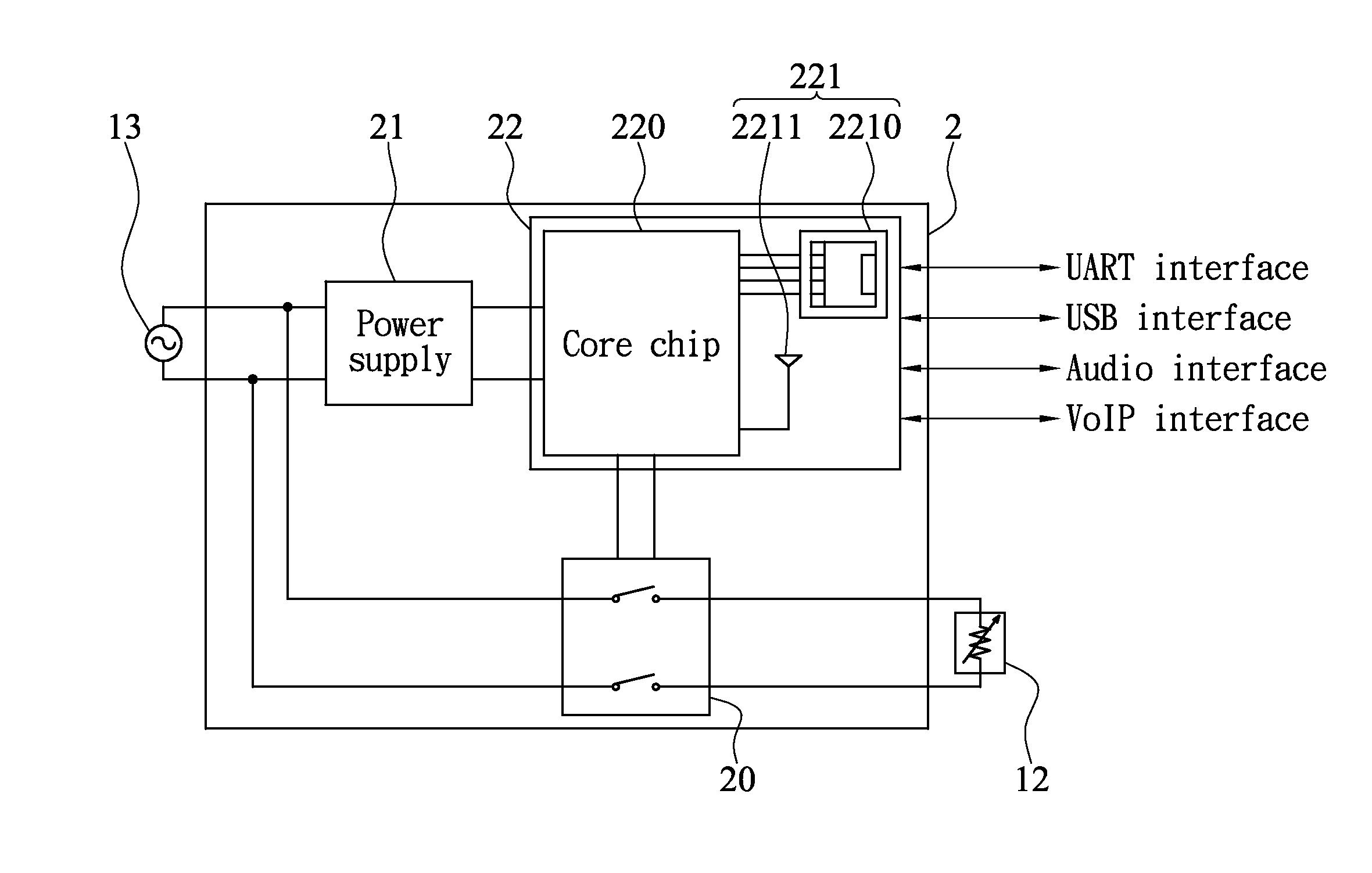
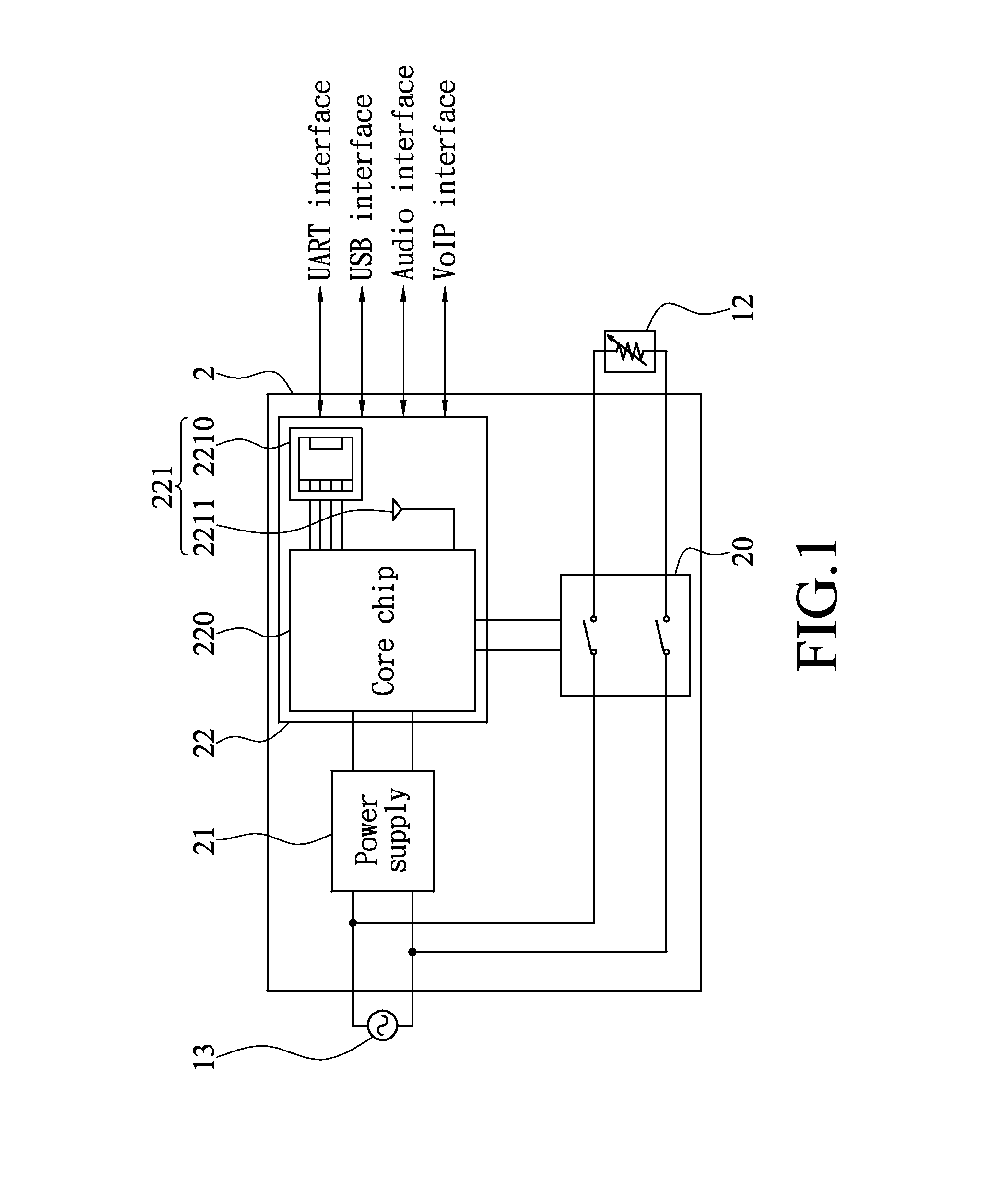
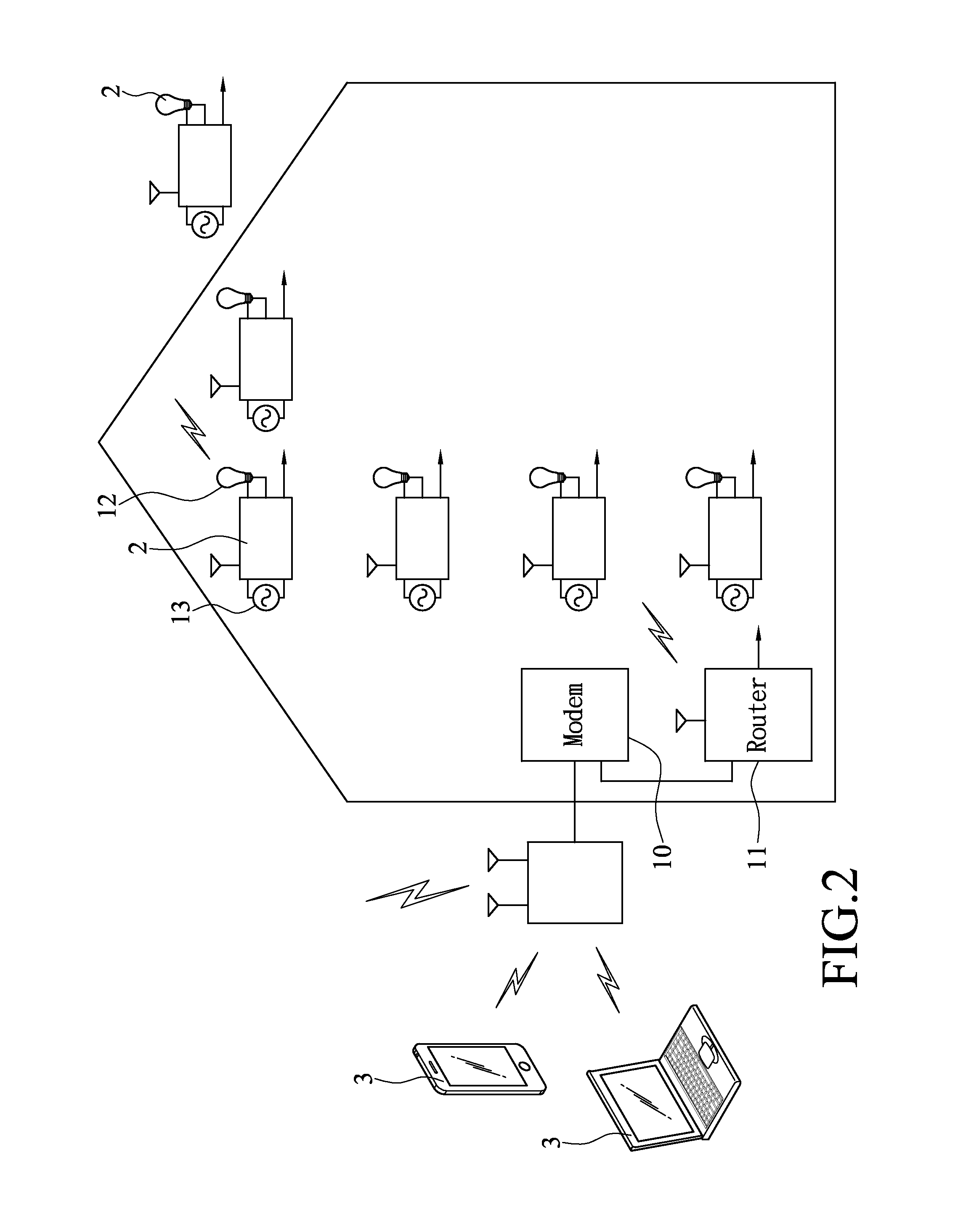
[0020]With reference to FIGS. 1 to 3 for block diagrams and a schematic view of an application of different embodiments of the present invention, when an ADSL circuit is installed in an area such as a residential area, a courtyard or an office, computers can be connected to the internet via a modem 10 with a connected telephone line, or a cable or wireless router 11 is installed to establish an intranet, such that at least one electronic device 12 such as an LED lamp, a camera, a computer, a display or a television in an area can be connected with each other while linking to the internet. The network power control module 2 is an independent module comprising a switch 20, a power supply 21, a processor 22, an AC / DC converter 23 and a power switch 24, so that manufacturers can assemble the network power con...


PUM


Abstract

A network power control module includes a switch and a processor installed in at least one electronic device within an area. The switch is electrically coupled to a first external power supply and the electronic device, and the processor includes a communication module in electrical communication with a control device at a remote end via a router of the area for receiving a control signal and then switching the switch to output or stop outputting voltage of the first external power supply to the electronic device, so that users can control the electronic devices at a remote control freely without requiring complicated network configurations to facilitate the schedule management for household affairs and improve the users' comfortability and home security effectively.

Description

CROSS-REFERENCE TO RELATED APPLICATIONS[0001]This non-provisional application claims priority under 35 U.S.C. §119(a) on Patent Application No(s). 102200333 filed in Taiwan, R.O.C. on Jan. 8, 2013, the entire contents of which are hereby incorporated by reference.BACKGROUND OF THE INVENTION[0002]1. Field of the Invention[0003]The present invention relates to the field of remote control equipments, and more particularly to a simple-structured multifunctional network power control module installed between mains electricity and an electronic device to allow users to control the operation of the electronic device and the operation status timely.[0004]2. Description of the Related Art[0005]To facilitate users to use a home electric appliance such as air conditioner, television and stereo, a dedicated remote control is bundled or a universal remote control device compatible to the electric appliances is provided for users to operate the electric appliance via wireless transmission. Howeve...

Claims


Application Information

Patent Timeline
IPC IPC(8): H02J5/00
CPCH02J5/00Y02B90/2661Y04S40/127Y02B70/3266Y02B70/3275Y02B90/2653Y04S20/242Y04S20/244Y04S40/126H02J13/00016H02J13/00024H02J13/00026Y02B70/30Y04S20/221Y04S20/222Y02B70/3225H04N21/43615H04L12/2825H04L67/125H04L12/12H04L12/2818G06F1/266G06F1/3209H02J2310/14
Inventor WU, LAI-FU
Owner WU LAI FU
Why Eureka
Try Eureka