
System for Detecting Fluorescence and Projecting a Representative Image

Active Publication Date: 2014-07-03
ACCUVEIN
View PDF19 Cites 24 Cited by
  • Summary
  • Abstract
  • Description
  • Claims
  • Application Information

AI Technical Summary

Benefits of technology

The invention is about creating a device that can visualize invisible fluorescence using a special camera. This technology can help medical professionals see important information about tissues without having to shift their focus between the patient and a monitor. Additionally, it can improve the sensitivity, video frame rates, and depth of focus of existing fluorescent cameras. Furthermore, it can detect and convey information about multiple fluorophores in human tissues to the medical practitioner.

Problems solved by technology

Since the optical efficiency of fluorescence is usually quite low, emission light is usually much weaker than excitation light.
During open surgery, wherein the surgeon is directly viewing the field of surgery, utilization of a monitor is disadvantageous in the surgeon must glance away from the surgical site to view the image of the fluorescence.
This approach is disadvantaged in that it is cumbersome to operate without directly viewing the surgical site.
Further, when viewing the monitor the surgeon losses all three dimensional information that is normally obtained when directly viewing the surgical area.
While being valuable surgical and diagnostic tools, known fluorescent cameras suffer from a number of limitations, mostly stemming from very low signal levels produced by fluorescent dyes.
Those limitations are insufficient sensitivity, low video frame rates or long integration time necessary for taking a still image, as well as a limited depth of focus, especially if a large objective lens is used to alleviate sensitivity problems.

Method used


Image

  • System for Detecting Fluorescence and Projecting a Representative Image
  • System for Detecting Fluorescence and Projecting a Representative Image
  • System for Detecting Fluorescence and Projecting a Representative Image

Examples


Embodiment Construction

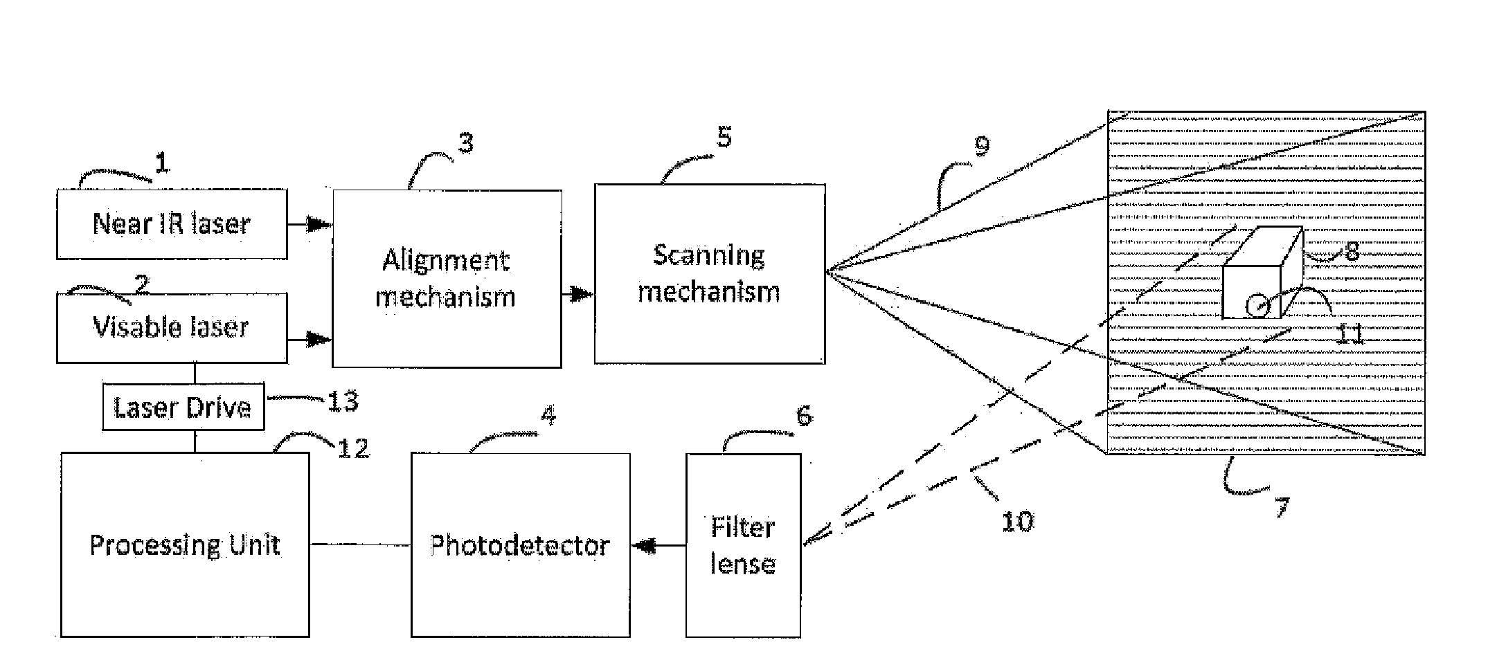
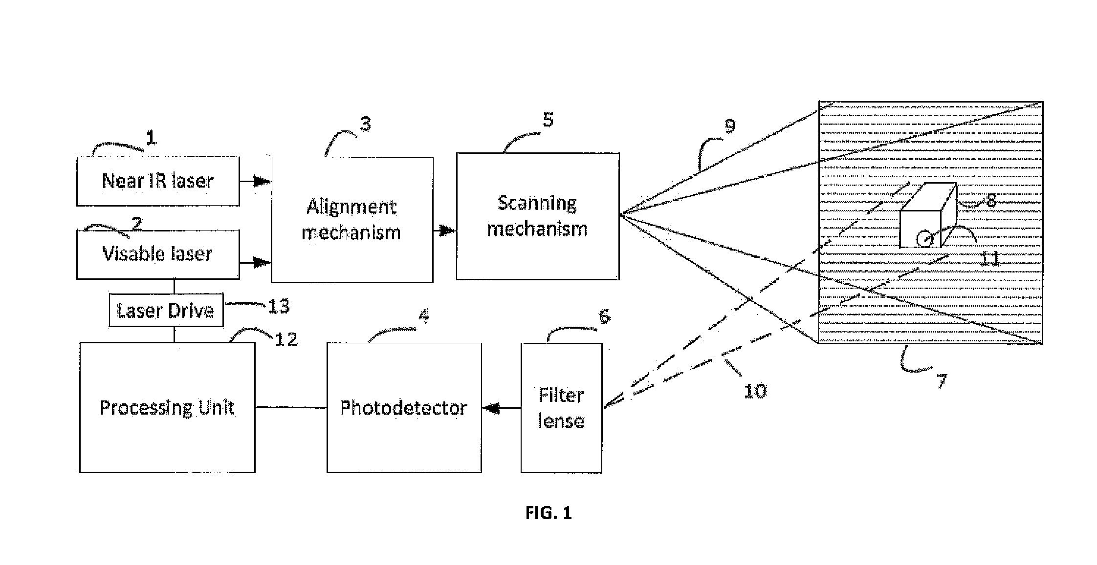
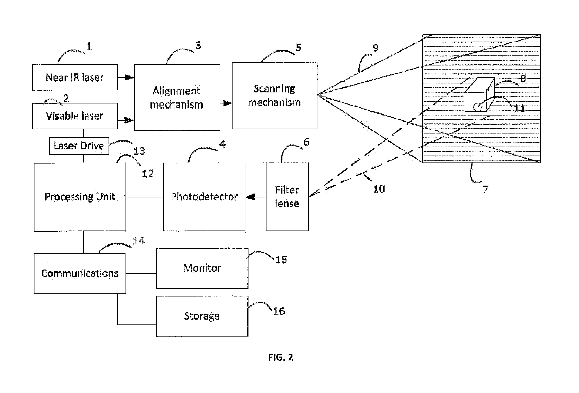
[0048]FIG. 1 shows a block diagram of a fluorescence imaging device capable of re-projecting fluorescence image directly on the human body, for example, during a surgery. A florescent dye, such as HER2Sense or RediJect 2-DG 750, which is available from Perkin Elmer in Waltham, Mass. (see, www.perkinelmer.com / catalog / category / id / Targeted), is delivered to the surgical area, via sub-cutaneous or intra-venous injection and accumulates in the objects of interest, for example cancer cells 11 of the patient.

[0049]A near IR laser 1 is provided at an IR frequency that is suitable for exciting the florescent dye in the cancer cells 11 of the surgical area. The near IR laser 1 passes through an alignment mechanism 3 which co axially aligns the near IR laser 1 with a visible laser 2. As a specific illustrative example, the near IR laser 1 could be a semiconductor laser diode which emits at 780 nm wavelength and the visible laser 2 can be a red laser that emits at a 640 nm wavelength. The coaxi...


PUM


Abstract

A fluorescence imaging device detects fluorescence in parts of the visible and invisible spectrum, and projects the fluorescence image directly on the human body, as well as on a monitor, with improved sensitivity, video frame rate and depth of focus, and enhanced capabilities of detecting distribution and properties of multiple fluorophores. Direct projection of three-dimensional visible representations of florescence on three-dimensional body areas advantageously permits view of it during surgical procedures, including during cancer removal, reconstructive surgery and wound care, etc. A NIR laser and a human visible laser (HVL) are aligned coaxially and scanned over the operating field of view. When the NIR laser passes over the area where the florescent dye is present, it energizes the dye which emits at a shifted NIR frequency detected by a photo diode. The HVL is turned on when emission is detected, providing visual indication of those positions.

Description

CROSS REFERENCE TO RELATED APPLICATIONS[0001]This application claims priority on U.S. Provisional Application Ser. No. 61 / 733,535 filed on Dec. 5, 2012, and claims priority on U.S. Provisional Application Ser. No. 61 / 830,225, filed on Jun. 3, 2013, with the disclosures of each incorporated herein by reference.FIELD OF INVENTION[0002]This invention is related to the field of fluorescent medical imaging.BACKGROUND OF INVENTION[0003]Fluorescence is a phenomenon of light emission by a substance that has previously absorbed light of a different wavelength. In most cases, the emitted light has a longer wavelength, and therefore lower energy, than the absorbed light. However, when the absorbed electromagnetic radiation is intense, it is possible for one atom or molecule to absorb two photons; this two-photon absorption can lead to emission of radiation having a shorter wavelength than the absorbed radiation. Fluorescent light can be easily separated from reflected excitation light, thus pr...

Claims


Application Information

Patent Timeline
IPC IPC(8): A61B5/00
CPCA61B2018/00577A61B5/0071A61B18/20A61B5/0077A61B5/742
Inventor WOOD, FREDYAVID, DMITRYZOTT, JOEGOLDMAN, RON
Owner ACCUVEIN
Learn More