
Automatic scanning and positioning apparatus for a scout image

a positioning apparatus and scout image technology, applied in the field of scanning positioning apparatus, can solve the problems of inability to execute the anticipated axial scanning, a lot of defects in the manual positioning of sinuses scan, and a lot of defects in the manual positioning of orbit scan, so as to increase the image throughput, save time, and increase the image speed

Active Publication Date: 2014-07-03
GE MEDICAL SYST GLOBAL TECH CO LLC
View PDF2 Cites 12 Cited by
  • Summary
  • Abstract
  • Description
  • Claims
  • Application Information

AI Technical Summary

Benefits of technology

The automatic scanning and positioning apparatus described in this patent saves time, increases imaging speed, and allows for higher image throughput within a given time period, while also avoiding excessive manpower consumption. Compared to manual positioning, the apparatus uses a multiple information fuzzy algorithm for more accurate and better imaging performance. When applied in orbit scanning, the apparatus also reduces the radiation dose of X-rays, potentially avoiding damage to human eyes. These technical effects provide a better user experience for clinicians.

Problems solved by technology

There exist a lot of defects in the manual positioning of sinuses scan.
There exist a lot of defects in the manual positioning of orbit scan.
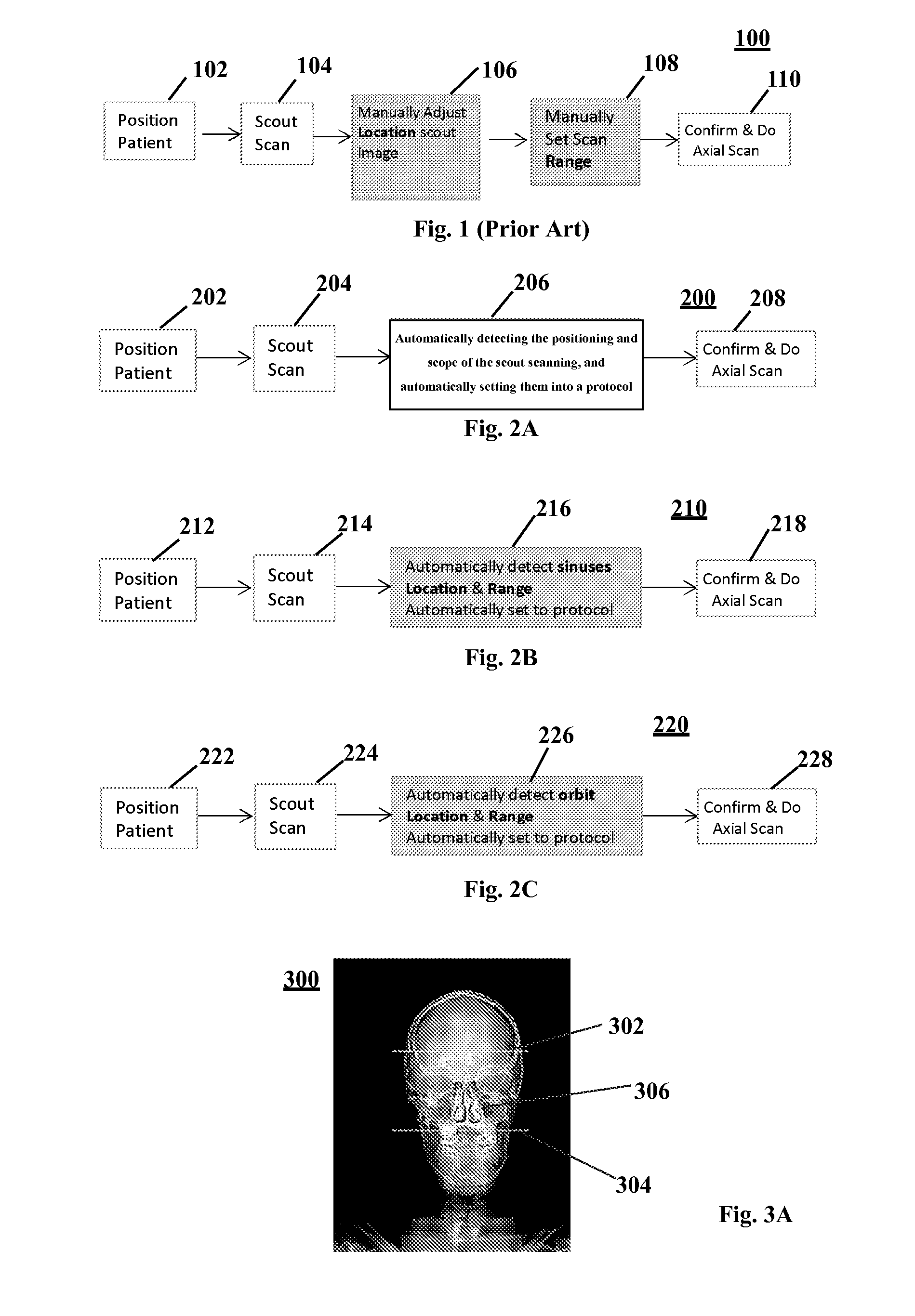
The currently known defects existing in the above manual positioning 100 of scout image (e.g., sinuses scan and orbit scan) include, but are not limited to: the manual positioning 100 takes time and efforts; it mainly relies on the doctor's experiences and vision; and in the case that the operator is not familiar enough with it, the manual positioning 100 may be inaccurate, and thus is unable to execute the anticipated axial scanning.
However, the above method focuses on the compensation of SPECT mode to CT mode, thereby realizing less dose and higher availability, but fails to solve the technical problem of automatically positioning scout image which is anticipated by this disclosure to be solved.
However, adjustments to the tilt image reconstruction range and the scan range for a non-tilt scan still need to manually conducted, so the problem anticipated by the present disclosure to be solved cannot be solved by the above application.

Method used


Image

  • Automatic scanning and positioning apparatus for a scout image
  • Automatic scanning and positioning apparatus for a scout image
  • Automatic scanning and positioning apparatus for a scout image

Examples


Embodiment Construction

[0025]One or more embodiments of the present technique will be depicted below. In order to try to provide a concise depiction of these embodiments, the present description does not depict all features of real implementation. It should be aware that in the development of any such real implementation, during any engineering project or design project, manifold decisions for realizing specifics must be made so as to achieve specific goals of developers, e.g., to be consistent with system-related and business-related constraints, which may vary depending on different implementations. Furthermore, it should be aware that, for persons skilled in the art who are benefit from this disclosure, such a development achievement may be complicated and time consuming, but in spite of such, is still a routine in design, manufacture and process.

[0026]An element or step as used herein which is quoted in a singular form and follows an indefinite article “a / an”, shall be construed as not excluding multi...


PUM


Abstract

An automatic scanning and positioning apparatus for a scout image, comprising: a receiving means, for receiving a scout image of a subject obtained through scout scanning; a checking and determining means, for automatically checking at least one position in the scout image according to a plurality of information contained in the scout image, and automatically determining a scanning scope based on the at least one position; and an executing means, for executing axial scanning to the subject based on the determined scanning scope.

Description

TECHNICAL FIELD[0001]The present invention generally relates to a scanning and positioning apparatus in the medical field, more particularly, relates to an automatic CT scanning and positioning apparatus for human face scout image.BACKGROUND OF THE INVENTION[0002]Sinuses scan in hospitals are mainly used for diagnosing injury, deformity, malignant tumor and inflammation. A doctor firstly scans a scout image so as to localize the position of sinuses from a frontal sinus to a nose (including external nose, nasal cavity). Currently the above positioning is a manual operation completed by the doctor. The doctor needs to manually click or drag a mouse to change the start position and end position of the final axial scanning on the scout image. There exist a lot of defects in the manual positioning of sinuses scan.[0003]On the other hand, orbit scan in the hospitals are mainly used for the diagnosis of orbital structural diseases and orbital components, injuries and foreign objects. The d...

Claims


Application Information

Patent Timeline
IPC IPC(8): A61B6/00
CPCA61B6/52A61B6/488A61B6/032A61B6/501A61B6/545
Inventor CHEN, YUSISHI, YILUNLIU, PINGLI, YING
Owner GE MEDICAL SYST GLOBAL TECH CO LLC
Learn More