Gas sensing apapratus

a technology of gas sensing and sensors, applied in the field of gas sensors, can solve the problems of air being considered unacceptably polluted with a certain target gas, no sensors or sensor technologies that meet all the above requirements, and severe application problems

Active Publication Date: 2014-06-26
KONINKLIJKE PHILIPS ELECTRONICS NV
View PDF8 Cites 21 Cited by
  • Summary
  • Abstract
  • Description
  • Claims
  • Application Information

AI Technical Summary

Benefits of technology

The invention proposes a sensing arrangement with two separate gas sensors to detect a specific gas, and to equalize the sensor responses when exposed to the same gas. This compensates for any differences in sensor response due to the target gas concentration, interfering gases, temperature, and humidity. The technical effect is improved accuracy in gas sensing.

Problems solved by technology

Lack of sufficient selectivity remains a key issue with all major sensor technologies and poses severe application problems in ordinary indoor environments where usually an unknown mixture of different gaseous pollutants is present.
Air is considered to be unacceptably polluted with a certain target gas when the concentration of that target gas is comparable to or higher than its recommended maximum concentration limit.
At present, no sensors or sensor technologies exist that fulfill all the above requirements to a satisfactory extent.
However, an important problem with metal-oxide semiconducting sensors and electrochemical sensors is their lack of selectivity.
However, pollutants tend to influence measurements directed at other pollutants.
A disadvantage of this approach is that it requires knowledge of the identity of the “other” pollutants.
However, it is usually not a priori known which gaseous pollutants interfere and the extent to which they interfere with the measurement of the target gas.
Furthermore, gases of widely different physical properties such as H2 and ethanol are known to be interfering gases for electrochemical formaldehyde sensors and it is far from easy to effectively remove all these gases from air at room temperature using small low-cost passive filters.
It is therefore in general very difficult or even impossible to design a practical filter capable of removing all interfering gases from air while leaving everything else the same.
A disadvantage of this approach is that the two filters can only be exchanged manually, which is inconvenient.
The useful lifetime of the formaldehyde filter is therefore only short and not practical in ordinary indoor environments.
In addition, the impregnation of the fibrous sheet filter with the reactant material results in an inevitable reduction of the filter porosity, thereby changing its diffusion barrier characteristics.
The afore-mentioned circumstances result in serious interpretation difficulties with respect to the obtained signal difference in terms of the ambient formaldehyde concentration and lead to large inaccuracies.
A disadvantage of the solution offered by Huarui is that effectively two separate working electrodes are needed within a single electrochemical sensor, as illustrated in FIG. 1.
It is therefore generally difficult, if not impossible, to unambiguously interpret the obtained differential sensor signal in terms of the target gas concentration.
Because the filters are integrated within the electrochemical sensor, it is not feasible to remove or otherwise manipulate them, for instance for sensor calibration purposes.

Method used


Image

  • Gas sensing apapratus
  • Gas sensing apapratus
  • Gas sensing apapratus

Examples


first embodiment

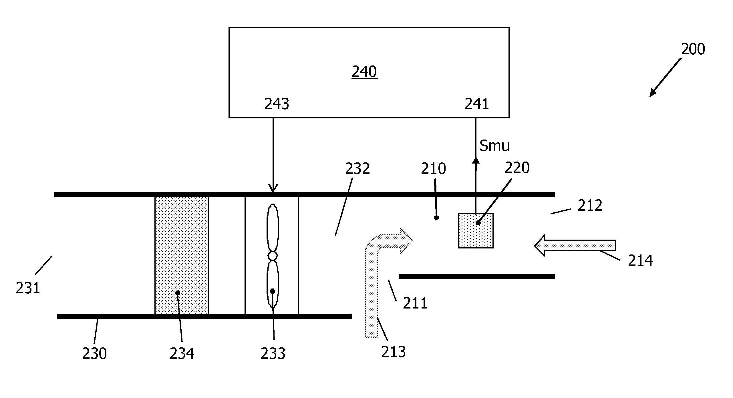
[0035]a gas sensing apparatus according to the present invention is generally indicated by reference numeral 200 and is schematically illustrated in FIGS. 3A and 3B. The gas sensing apparatus 200 comprises a measuring chamber 210 and a gas sensor 220 arranged in the measuring chamber 210.

[0036]The measuring chamber 210 has at least one passageway 211 allowing direct entry of ambient air and allowing this ambient air to reach the measuring chamber 210 unfiltered. In the embodiment shown, there are two different passageways 211, 212 connecting the measuring chamber 210 to the ambient environment such as to allow for convection.

[0037]The gas sensing apparatus 200 further comprises an air duct 230 having an entrance 231 communicating with the ambient environment and an output 232 communicating with the measuring chamber 210. The gas sensing apparatus 200 further comprises a gas filter 234 and a controllable airflow generating means 233, for instance a ventilator, arranged in the air duc...

embodiment 300

[0054]The six ducts 610-660 together define three pairs of ducts 610, 640; 620, 650; 630, 660. The ducts of each pair are arranged in such a way that their respective second openings 612, 642; 622, 652; 632, 662 are located on opposite sides of the measuring chamber 210. The control device is designed such as to selectively operate one of said pairs of ducts, with the other pairs being out of operation. Then, such a selected pair of ducts behaves like the embodiment 300 discussed with reference to FIG. 5. FIG. 8 illustrates this for the ducts 610 and 640: by appropriate control of the corresponding ventilators 614, 644, ambient air flows from opening 611 via measuring chamber 210 towards opening 641, as shown by arrows, or in the opposite direction, so the sensor 220 is exposed to air selectively filtered by either filter 613 or filter 643, respectively. Likewise, the ducts 620 and 650 form an associated pair: by appropriate control of the corresponding ventilators 624, 654, ambient...


PUM


Abstract

A method of selectively sensing the concentration of a target gas in polluted ambient air comprises the steps of: —providing a target gas sensor (220) sensitive to the target gas; —providing a first gas flow derived from the ambient air, from which first flow the target gas is substantially removed; —providing a second gas flow derived from the ambient air, substantially comprising the same target gas concentration as the ambient air; —exposing the target gas sensor to the first gas flow during a first time interval, and obtaining from the sensor a first output signal (Smf); —exposing the target gas sensor to the second gas flow during a second time interval not overlapping with the first time interval, and obtaining a second output signal (Smu); —calculating the difference (SΔ) between the first and the second output signals; calculating the concentration of the target gas from the calculated signal difference (SΔ).

Description

FIELD OF THE INVENTION[0001]The present invention relates in general to the field of gas sensors.BACKGROUND OF THE INVENTION[0002]An important application of gas sensors lies in the domain of indoor air pollution monitoring, only for obtaining objective data, and control of air handling units and / or air cleaning units. It would be desirable that such a sensor has the following features:[0003]small size;[0004]low cost;[0005]low power requirements;[0006]minimal maintenance requirements over an operational period of at least several years;[0007]a combination of high sensitivity and high selectivity with respect to a particular target gas or target class of gases.[0008]Selectivity is especially important in situations where the composition of the gas to be measured is not known in advance. Lack of sufficient selectivity remains a key issue with all major sensor technologies and poses severe application problems in ordinary indoor environments where usually an unknown mixture of differen...

Claims


Application Information

Patent Timeline
IPC IPC(8): G01N27/403
CPCG01N27/403G01N1/2273G01N27/4045G01N33/0006
Inventor MARRA, JOHANKLOOTWIJK, JOHAN HENDRIKGIESBERS, JACOBUS BERNARDUSDE WILD, NICO MARIS ADRIAANBULDER, MARCELNIESSEN, ROGIE ADRIANUS HENRICAVAN DER LINDE, PETER
Owner KONINKLIJKE PHILIPS ELECTRONICS NV
Why Eureka
Try Eureka