Flexible diaphragm combination floating and rigid abrading workholder

a flexible diaphragm and workholder technology, applied in the field of abrasive treatment of surfaces, can solve the problems of large cost savings and high workpiece production ra

Inactive Publication Date: 2014-06-19
DUESCHER WAYNE O
View PDF42 Cites 10 Cited by
  • Summary
  • Abstract
  • Description
  • Claims
  • Application Information

AI Technical Summary

Benefits of technology

[0023]The presently disclosed technology includes precision-thickness flexible abrasive disks having disk thickness variations of less than 0.0001 inches (3 microns) across the full annular bands of abrasive-coated raised islands to allow flat-surfaced contact with workpieces at very high abrading speeds. Use of a rotary platen vacuum flexible abrasive disk attachment system allows quick set-up changes where different sizes of abrasive particles and different types of abrasive material can be quickly attached to the flat platen surfaces.
[0025]Water coolant is used with these raised island abrasive disks, which allows them to be used at very high abrading speeds, often in excess of 10,000 SFPM (160 km per minute). The same types of chemicals that are used in the conventional CMP polishing of wafers can be used with this abrasive lapping or polishing system. These liquid chemicals can be applied as a mixture with the coolant water that is used to cool both the wafers and the fixed abrasive coatings on the rotating abrading platen This mixture of coolant water and chemicals continually washes the abrading debris away from the abrading surfaces of the fixed-abrasive coated raised islands which prevents unwanted abrading contact of the abrasive debris with the abraded surfaces of the wafers.
[0026]Slurry lapping is often done at very slow abrading speeds of about 5 mph (8 kph). By comparison, the high speed flat lapping system often operates at or above 100 mph (160 kph). This is a speed difference ratio of 20 to 1. Increasing abrading speeds increase the material removal rates. High abrading speeds result in high workpiece production rates and large cost savings.
[0028]Also, these conventional rotating offset spherical-action workholders are nominally unstable at very high rotation speeds, especially when the workpieces are not held firmly in direct flat-surfaced contact with the platen abrading surface. It is necessary to provide controlled operation of these unstable spherical-action workholders to prevent unwanted vibration or oscillation of the workholders (and workpieces) at very high rotational speeds of the workholders. Vibrations of the workholders can produce patterns of uneven surface wear of an expensive semiconductor wafer.
[0030]The slide-pin arm driven workholders having flexible annular diaphragm or flexible bellows chamber devices provide that a wide range of uniform abrading pressures can be applied across the full abraded surfaces of the workpieces such as semiconductor wafers.
[0032]Conventional flexible elastomeric pneumatic-chamber wafer carrier heads have a substantial disadvantage in that the vertical walls of the elastomeric chambers are very weak in a lateral or horizontal direction. The abrading pressures and vacuum that are applied to these sealed chambers are typically very small, in part, to avoid very substantial lateral deflections of the elastomer walls. The sealed abrading-chamber annular flexible diaphragm device 237 described here are flexible which allows axial motion of the workholder.

Problems solved by technology

High abrading speeds result in high workpiece production rates and large cost savings.

Method used


Image

  • Flexible diaphragm combination floating and rigid abrading workholder
  • Flexible diaphragm combination floating and rigid abrading workholder
  • Flexible diaphragm combination floating and rigid abrading workholder

Examples


Embodiment Construction

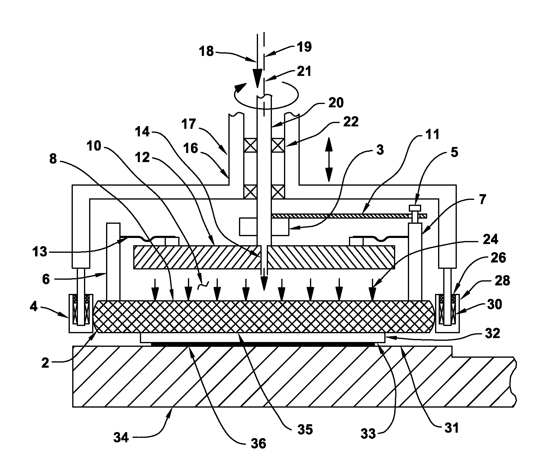
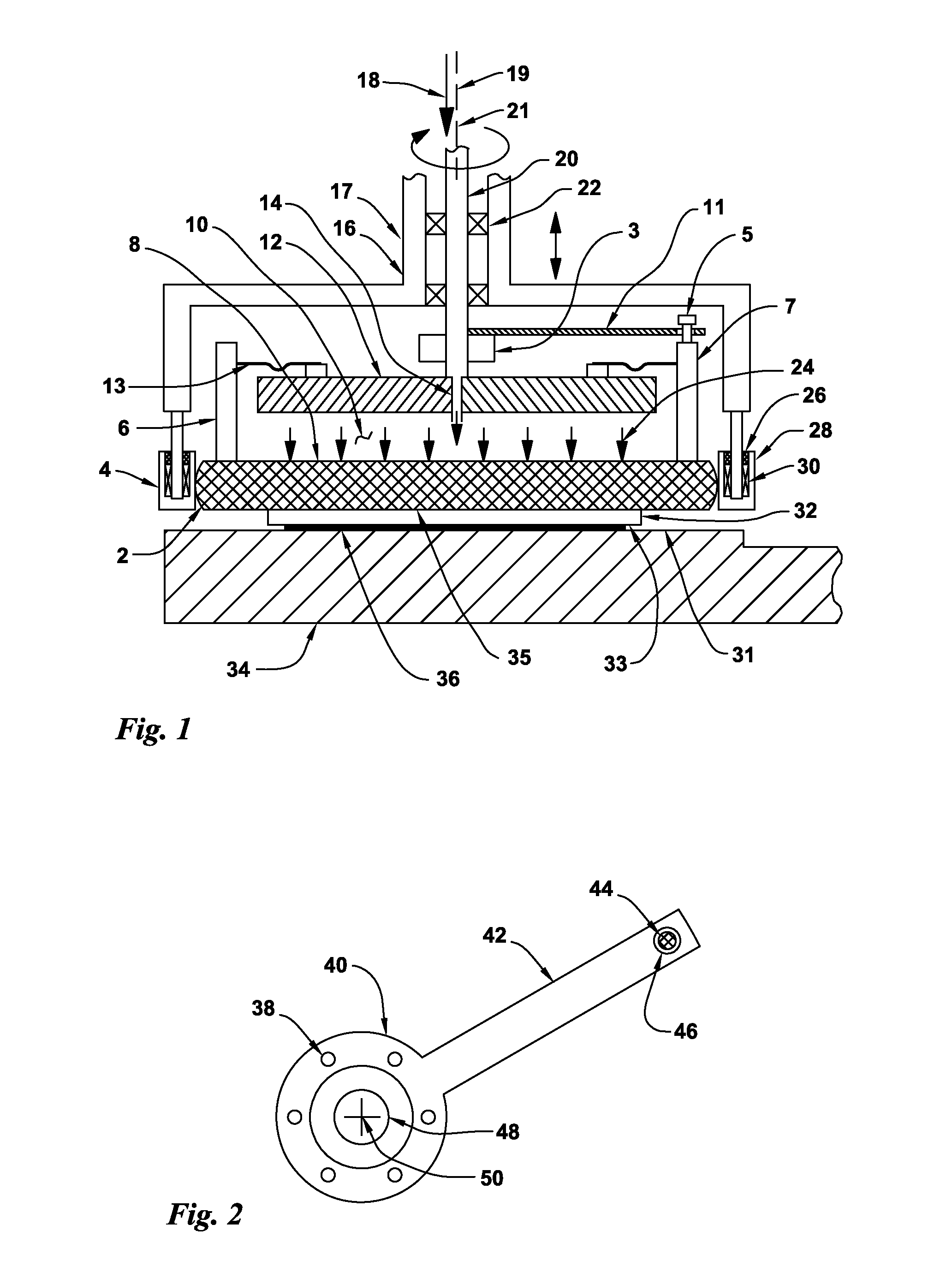
[0058]FIG. 1 is a cross section view of a pin driven flexible diaphragm workpiece carrier used for lapping or polishing semiconductor wafers or other workpiece substrates. A stationary workpiece carrier head 17 has a flat-surfaced workpiece 32 that is attached to a floating workpiece carrier rotor 35 that is rotationally driven by a drive-pin device 5. A nominally-horizontal drive plate 12 is attached to a hollow drive shaft 20 having a rotation axis 19 that is supported by bearings 22 that are supported by a stationary carrier housing 16 where the carrier housing 16 can be raised and lowered in a vertical direction.

[0059]A nominally-rigid rotational drive arm 11 is attached to the hollow drive shaft 20 where rotation of the hollow drive shaft 20 rotates the rotational drive arm 11. The drive-pin device 5 is attached a rigid annular member 6 or multiple individual posts 7 that is / are attached to the workpiece carrier rotor 35 which allows the drive-pin device 5 to rotationally drive...


PUM

PropertyMeasurementUnit
thicknessaaaaaaaaaa
pressureaaaaaaaaaa
pressuresaaaaaaaaaa

Abstract

Flat-surfaced workpieces such as semiconductor wafers or sapphire disks are attached to a rotatable floating or rigid workpiece holder carrier that is supported by a pressurized-air flexible elastomer disk sealed air-chamber device and is rotationally driven by a flexible arm or a lug-pin device. The rotating wafer carrier rotor is horizontally restrained by a set of idlers that are attached to a stationary housing to provide rigid support against abrading forces. The abrading system can be operated at the very high abrading speeds used in high speed flat lapping with raised-island abrasive disks. A wide range of abrading pressures are applied uniformly across the surface of the workpiece. Vacuum can also be applied to the elastomer chamber to quickly move the wafer away from the abrading surface. Internal constraints limit the axial, lateral and circumferential motion of the workholder. Wafers can be quickly attached to the workpiece carrier with vacuum.

Description

CROSS REFERENCE TO RELATED APPLICATIONS[0001]This invention is a continuation-in-part of U.S. patent application Ser. No. 14 / 154,133 filed Jan. 13, 2014 that is a continuation-in-part of U.S. patent application Ser. No. 14 / 148,729 filed Jan. 7, 2014 that is a continuation-in-part of U.S. patent application Ser. No. 13 / 869,198 filed Apr. 24, 2013 that is a continuation-in-part of U.S. patent application Ser. No. 13 / 662,863 filed Oct. 29, 2012. These are each incorporated herein by reference in their entirety.BACKGROUND OF THE INVENTIONField of the Invention[0002]The present invention relates to the field of abrasive treatment of surfaces such as grinding, polishing and lapping. In particular, the present invention relates to a combination-type high speed semiconductor wafer or abrasive lapping or polishing workholder system for use with single-sided abrading machines that have rotary abrasive coated flat-surfaced platens. The spider arm and slide-pin drive workholders employed here a...

Claims


Application Information

Patent Timeline
Patent Type & Authority Applications(United States)
IPC IPC(8): B24B37/30H01L21/304B24B37/10
CPCB24B37/10B24B37/30B24B37/32B24B37/042H01L21/304
Inventor DUESCHER, WAYNE O.
Owner DUESCHER WAYNE O
Why Eureka
Try Eureka