Power module package
a power module and package technology, applied in the field of power module packages, can solve the problems of inability to easily access, high cost, and limited underground resources, and achieve the effect of simplifying the process and reducing costs
- Summary
- Abstract
- Description
- Claims
- Application Information
AI Technical Summary
Benefits of technology
Problems solved by technology
Method used
Image
Examples
first preferred embodiment
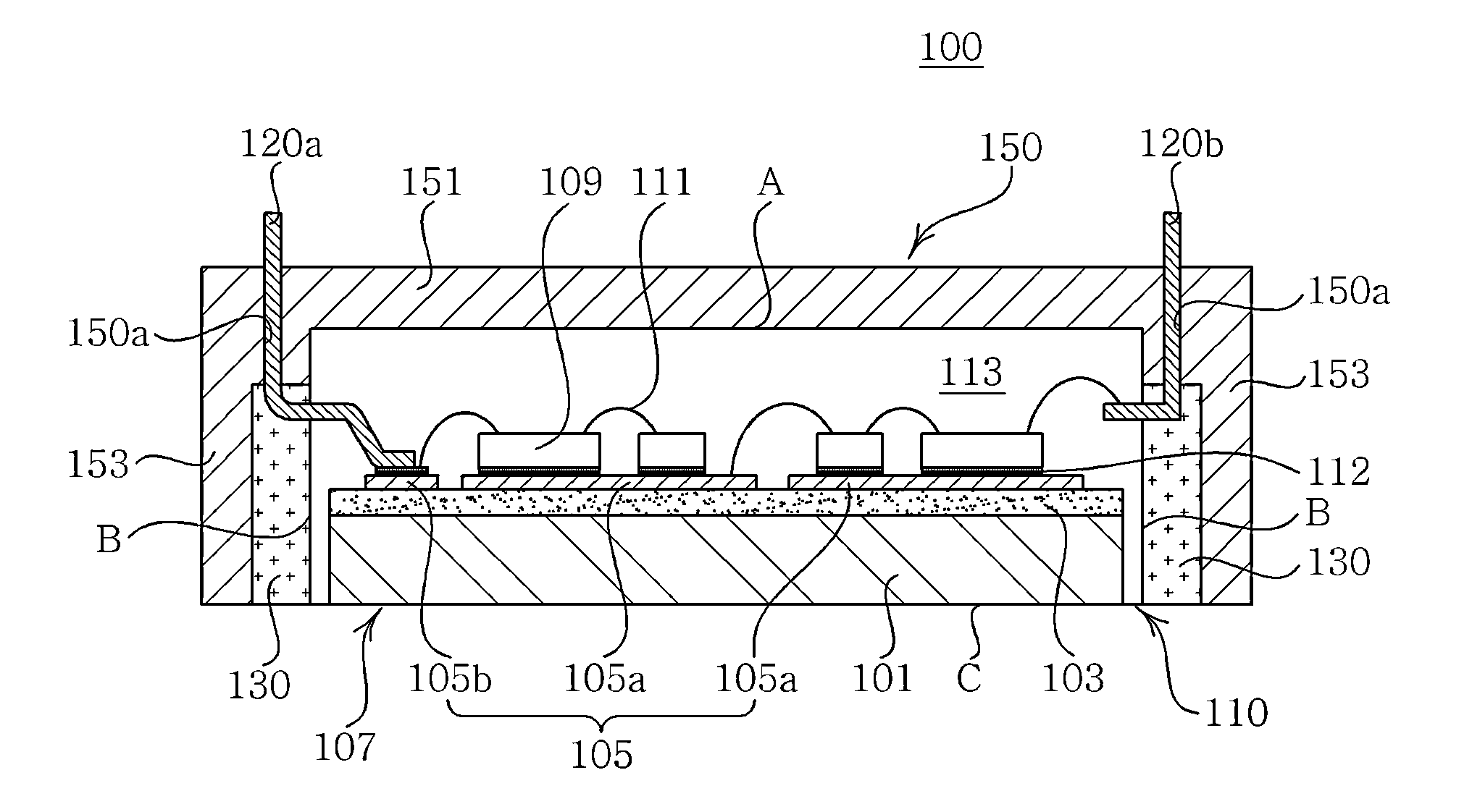
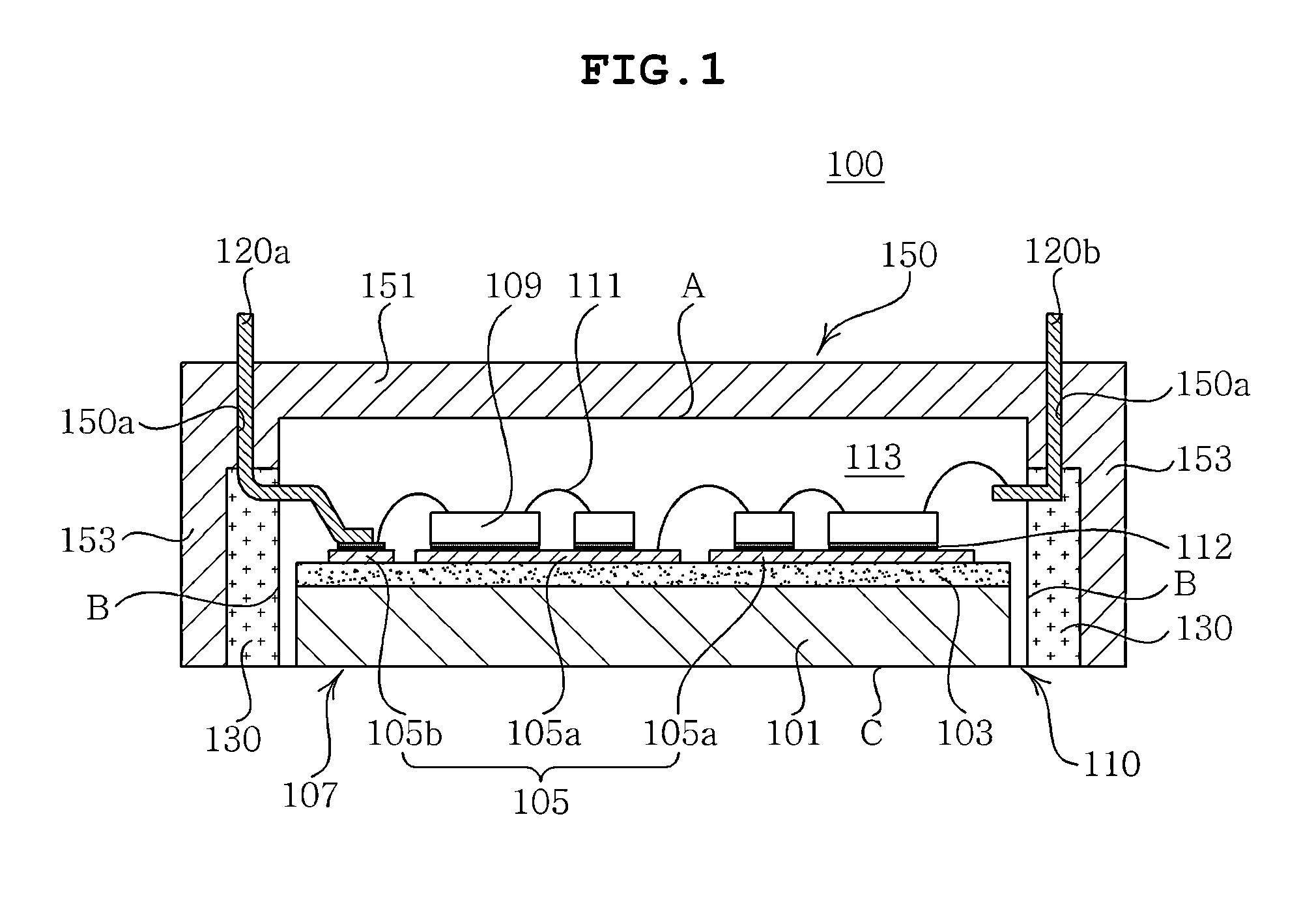
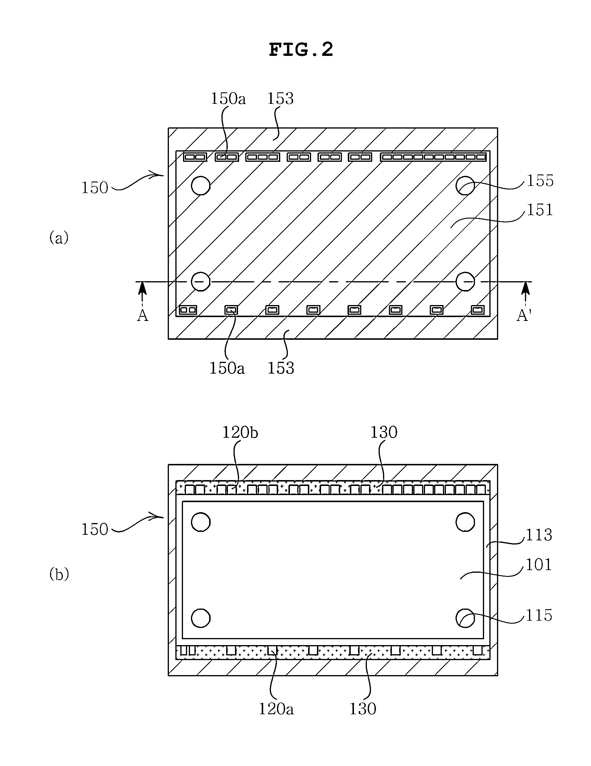
[0046]FIG. 1 is a cross-sectional view showing a structure of a power module package according to a first preferred embodiment of the present invention, FIG. 2 is a plan view showing a top surface and a bottom surface of the power module package of FIG. 1, FIGS. 3 and 4 each are a cross-sectional view of the line A-A′ of FIG. 2 and cross-sectional views showing a structure with which a first fastening member is fastened, FIGS. 5 and 6 each are a cross-sectional view showing a structure of a fastening groove formed in the power module package of FIG. 1 and a cross-sectional view showing a structure in which a second fastening member is fastened with the fastening groove, and FIGS. 7 and 8 are cross-sectional views of a structure in which a third fastening member protruded from an inner wall of a case of the power module package of FIG. 1 is fastened with the first module.
[0047]Referring to FIG. 1, a power module package 100 according to the preferred embodiment of the present inventi...
second preferred embodiment
[0106]FIG. 9 is a cross-sectional view showing a structure of a power module package according to a second preferred embodiment of the present invention.
[0107]The description of overlapping components with the foregoing first preferred embodiment of the present invention will be omitted in the second preferred embodiment of the present invention. Further, the overlapping components with the first preferred embodiment of the present invention are denoted by the same reference numerals.
[0108]Referring to FIG. 9, a power module package 200 according to the preferred embodiment of the present invention may include the first module 110, the second module 180 disposed on the first module 110, and the case 150 enclosing the first module 110 and the second module.
[0109]Further, the power module package may further include a bonding member (not shown) formed between the first module 110 and the second module 180.
[0110]The first module 110 according to the preferred embodiment of the present ...
third preferred embodiment
[0124]FIG. 10 is a cross-sectional view showing a structure of a power module package according to a third preferred embodiment of the present invention.
[0125]The description of overlapping components with the foregoing second preferred embodiment of the present invention will be omitted in the third preferred embodiment of the present invention. Further, the overlapping components with the second preferred embodiment of the present invention are denoted by the same reference numerals.
[0126]Referring to FIG. 10, a power module package 300 according to the preferred embodiment of the present invention may include the first module 110, the second module 180 disposed on the first module 110, and the case 150 enclosing the first module 110 and the second module 180.
[0127]Further, the power module package 300 may further include a bonding member (not shown) formed between the first module 110 and the second module 180.
[0128]The first module 110 according to the preferred embodiment of th...
PUM
 Abstract
Description
Claims
Application Information
 - R&D
- Intellectual Property
- Life Sciences
- Materials
- Tech Scout
- Unparalleled Data Quality
- Higher Quality Content
- 60% Fewer Hallucinations
Browse by: Latest US Patents, China's latest patents, Technical Efficacy Thesaurus, Application Domain, Technology Topic, Popular Technical Reports.
© 2025 PatSnap. All rights reserved.Legal|Privacy policy|Modern Slavery Act Transparency Statement|Sitemap|About US| Contact US: help@patsnap.com


