Lubricating oil supply apparatus

a technology of lubricating oil and supply apparatus, which is applied in the direction of battery/cell propulsion, gearing details, transportation and packaging, etc., can solve problems such as power loss, and achieve the effect of reducing power loss

Inactive Publication Date: 2014-06-05
TOYOTA JIDOSHA KK
View PDF12 Cites 12 Cited by
  • Summary
  • Abstract
  • Description
  • Claims
  • Application Information

AI Technical Summary

Benefits of technology

[0017]According to this structure, lubricating oil is able to be supplied from the tank to a portion of the gear mechanism through the communication hole, so a portion of the gear mechanism is able to be well lubricated even when a pump that draws up lubricating oil from the lub...

Problems solved by technology

As a result, there is a large amount of lubricating oil agitatin...

Method used


Image

  • Lubricating oil supply apparatus
  • Lubricating oil supply apparatus
  • Lubricating oil supply apparatus

Examples


Embodiment Construction

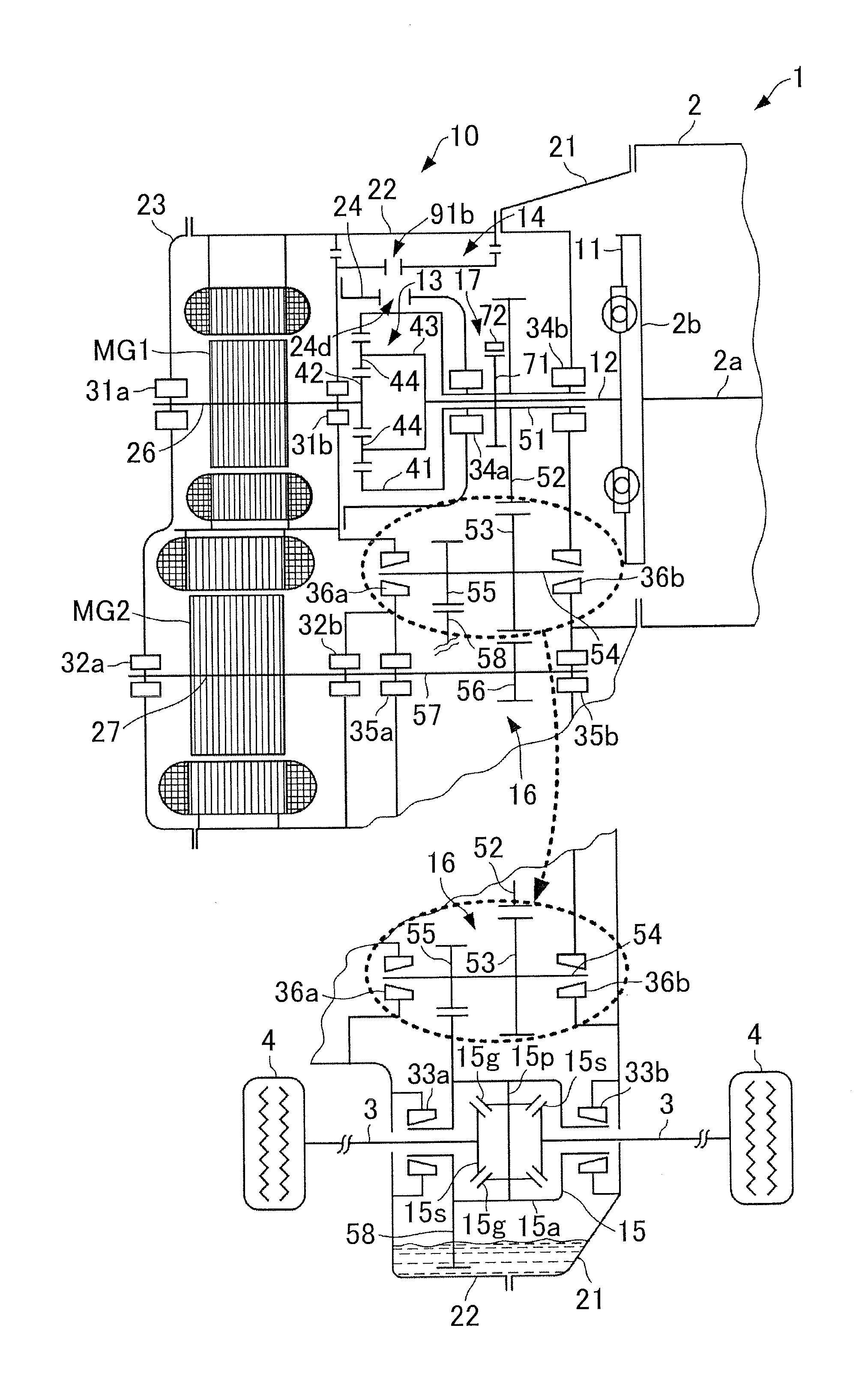
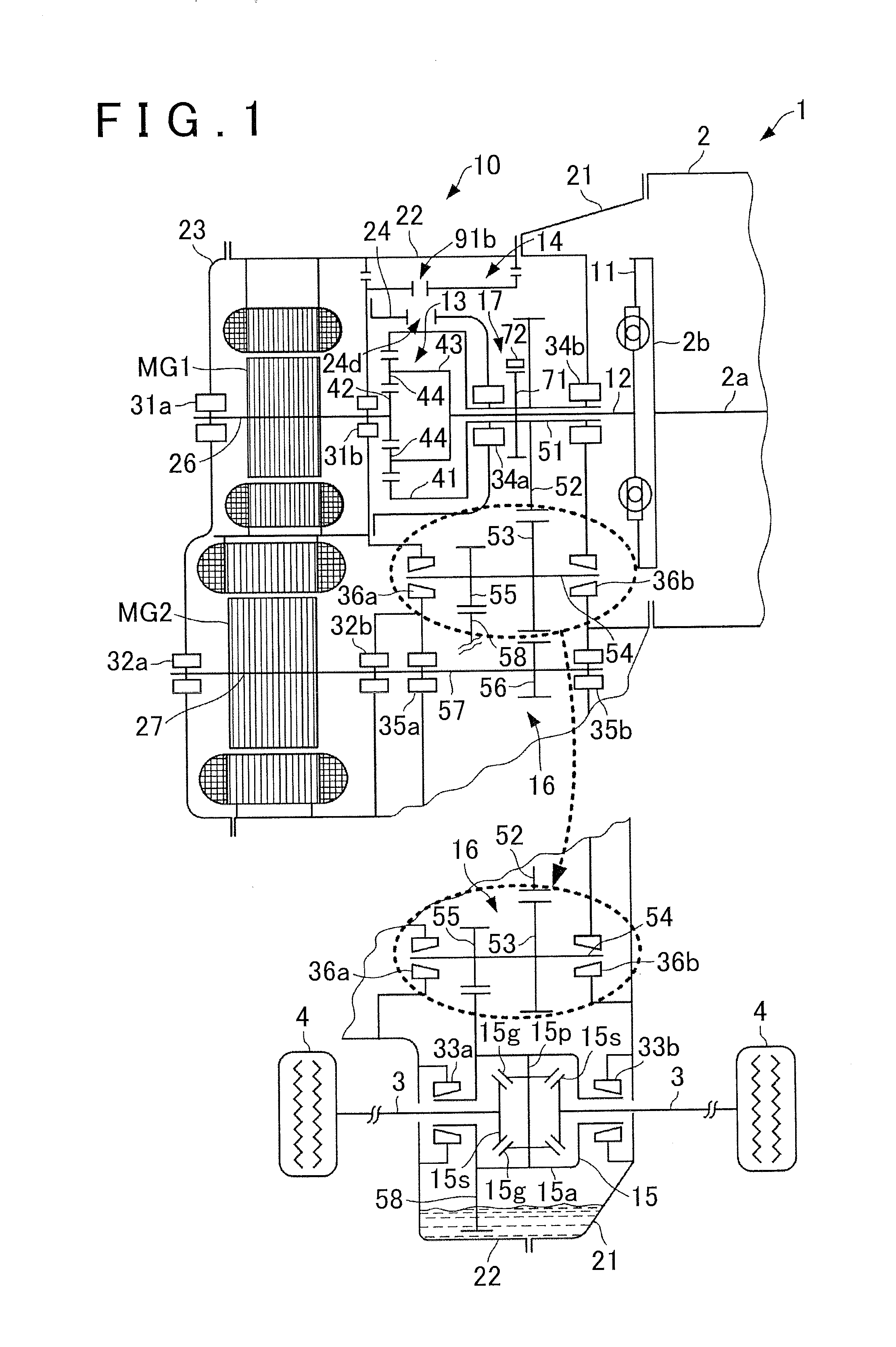
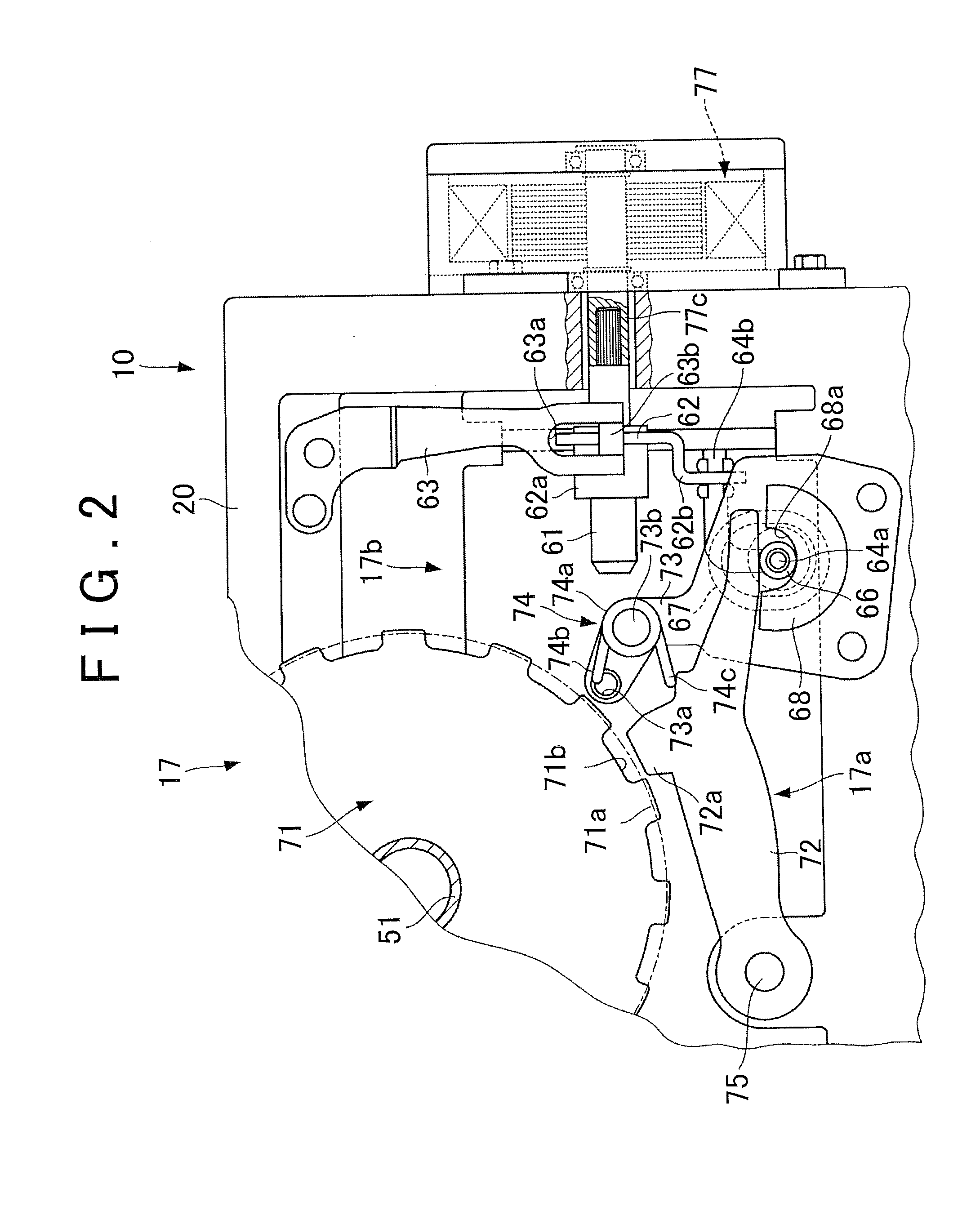
[0029]Hereinafter, example embodiments of the invention will be described with reference to the accompanying drawings. FIGS. 1 to 9 are views of a lubricating oil supply apparatus (lubricating oil supply structure) according to one example embodiment of the invention. FIG. 1 is a view of the structure of a drive apparatus provided with the lubricating oil supply apparatus according to this example embodiment of the invention.

[0030]As shown in FIG. 1, a drive apparatus 10 is configured as a transaxle of a hybrid vehicle 1 that is driven by one or both of an engine that is driven by fuel and a motor-generator as a rotary electric machine.

[0031]The vehicle 1 is a Front engine Front drive (FF) vehicle, and includes an engine 2 as an internal combustion engine, the drive apparatus 10, left and right drive shafts 3 that are connected to the drive apparatus 10, left and right wheels 4 that are connected to the left and right drive shafts 3, and an electronic control unit (ECU), not shown, ...


PUM


Abstract

A lubricating oil supply apparatus arranged in a transaxle case includes a differential ring gear, a catch tank that stores lubricating oil picked up by the differential ring gear, a first flow path arranged higher than a highest position of an outer diameter of the differential ring gear, a gear with a higher center position than the differential ring gear, and a second flow path that guides the lubricating oil picked up by the gear to the catch tank. The first flow path guides the lubricating oil picked up by the differential ring gear to the catch tank. The gear is in mesh with the differential ring gear, and picks up the lubricating oil picked up by the differential ring gear. The second flow path is arranged lower than a highest position of an outer diameter of the gear.

Description

INCORPORATION BY REFERENCE[0001]The disclosure of Japanese Patent Application No. 2012-266309 filed on Dec. 5, 2012 including the specification, drawings and abstract is incorporated herein by reference in its entirety.BACKGROUND OF THE INVENTION[0002]1. Field of the Invention[0003]The invention relates to a lubricating oil supply apparatus that stores lubricating oil picked up by a differential ring gear, in a catch tank.[0004]2. Description of Related Art Japanese Patent Application Publication No. 2010-242783 (JP 2010-242783 A), for example, describes one such known lubricating oil supply apparatus that includes a first guide passage that guides lubricating oil to a catch tank when a differential ring gear rotates at a high speed, and a second guide passage that guides lubricating oil to the catch tank when the differential ring gear rotates at a low speed. When the differential ring gear rotates at a low speed, the lubricating oil is picked up by the differential ring gear and t...

Claims


Application Information

Patent Timeline
IPC IPC(8): F16H57/04
CPCF16H63/3425F16H57/0409F16H57/0447F16H57/0457F16H57/0483B60L1/003B60L15/2054B60L2240/30B60L2240/421B60L2240/423B60L2240/486Y02T10/72B60L50/61B60L50/16F16H57/045Y02T10/62Y02T10/64Y02T10/7072Y02T10/70
Inventor KIMURA, HIROMICHIOBATA, TATSUOKATO, SHINGOAOKI, YUYA
Owner TOYOTA JIDOSHA KK
Why Eureka
Try Eureka