
Apparatus and method for calculating flicker-evaluation value

a technology of flicker and value, applied in the field of apparatus and a method for calculating flickerevaluation value, can solve the problems of synthetic image becoming an image difficult to see, flicker occurring in the short exposure image, image distortion when synthesizing image, etc., and achieve the effect of accurate detection

Active Publication Date: 2014-06-05
HANWHA TECHWIN CO LTD
View PDF0 Cites 41 Cited by
  • Summary
  • Abstract
  • Description
  • Claims
  • Application Information

AI Technical Summary

Benefits of technology

This patent describes a method for detecting and avoiding flickering in images and videos. By calculating a flicker-evaluation value for each pixel, the method can determine if flickering is present and select a long exposure image to avoid it. Additionally, the method can accurately detect flicker areas in order to create a flicker-free moving picture that has been processed for wider dynamic range. Overall, this technology ensures smoother and more stable video and image content.

Problems solved by technology

However, two types of problems occur in a structure of the related art which synthesizes the short exposure image and the long exposure image.
In the first problem, if a subject moves, an image is distorted when synthesizing images.
In the second problem, flicker occurs in the short exposure image.
Thus, the synthetic image becomes an image which is difficult to be seen.
A fluorescent lamp having no inverter may cause flicker.
The glimmering of the LED lamp at such a low frequency may be a factor causing flicker.
However, glimmering of the backlight may cause flicker.
Thus, the related art technique may not cope with a situation where a flicker light source starts or ends lighting when capturing a moving picture.
If a flicker light source having a high luminance is used, information about the high luminance may not be sufficiently acquired.

Method used


Image

  • Apparatus and method for calculating flicker-evaluation value
  • Apparatus and method for calculating flicker-evaluation value
  • Apparatus and method for calculating flicker-evaluation value

Examples


Embodiment Construction

[0049]Reference will now be made in detail to embodiments, examples of which are illustrated in the accompanying drawings, wherein like reference numerals refer to like elements throughout. In this regard, the present embodiments may have different forms and should not be construed as being limited to the descriptions set forth herein. Accordingly, the embodiments are merely described below, by referring to the figures, to explain aspects of the present description.

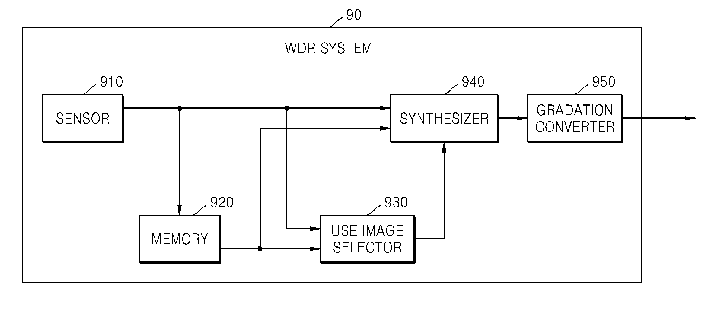
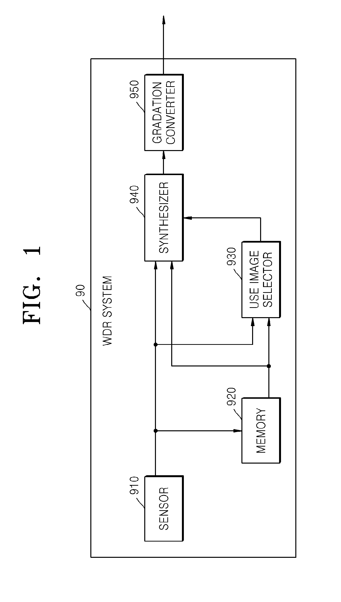
[0050]A related art wide dynamic range (WDR) system 90 will now be described. FIG. 1 is a block diagram illustrating a functional structure of the related art WDR system 90. The related art WDR system 90 changes exposure settings of a sensor 910 to continuously capture two images. The related art WDR system 90 performs short exposure capturing and then long exposure capturing. A short exposure image acquired through short exposure capturing is stored in a memory 920. If the short exposure capturing has ended, the related ...


PUM


Abstract

An apparatus and a method for calculating a flicker-evaluation value through a wide dynamic range (WDR) system. The apparatus includes: a first calculator configured to calculate a first difference between a pixel value of a long exposure image of a current frame and a pixel value of a long exposure image of a previous frame; an average calculator configured to calculate an average of the pixel value of the long exposure image of the current frame and the pixel value of the long exposure image of the previous frame; a second calculator configured to calculate a second difference between a pixel value of a short exposure image of the current frame and the average calculated by the average calculator; and a flicker-evaluation value calculator configured to calculate a flicker-evaluation value which indicates a flicker strength using the first difference and the second difference.

Description

CROSS-REFERENCE TO RELATED APPLICATIONS[0001]This application claims priority from Japanese Patent Application No. 2012-0265770, filed on Dec. 4, 2012, in the Japanese Patent Office and Korean Patent Application No. 10-2013-0091587, filed on Aug. 1, 2013, in the Korean Intellectual Property Office, the disclosures of which are incorporated herein in their entirety by reference.BACKGROUND[0002]1. Field[0003]One or more exemplary embodiments relate to an apparatus and a method for calculating a flicker-evaluation value. In particular, exemplary embodiments relate to an apparatus and a method for a flicker-evaluation value which is effective for wide dynamic range (WDR) processing for synthesizing a long exposure image and a short exposure image.[0004]2. Description of the Related Art[0005]A photographing function of the related art, such as a wide dynamic range (WDR) or a high dynamic range (HDR), has been used to continuously capture and synthesize a short-time exposure image (herein...

Claims


Application Information

Patent Timeline
IPC IPC(8): G06T7/00H04N5/235
CPCH04N5/2357G06T7/0022H04N23/741H04N23/745
Inventor TSUZUKI, TAKERU
Owner HANWHA TECHWIN CO LTD
Learn More