
Exponential Scan Mode for Quadrupole Mass Spectrometers to Generate Super-Resolved Mass Spectra

a mass spectrometer and scan mode technology, applied in the field of mass spectrometry, can solve the problems of increasing the cost of mass resolving power, and sensitivity, and achieves the effect of reducing overall cost, enhancing the performance of mass spectrometers, and little additional hardware cost or complexity

Active Publication Date: 2014-06-05
THERMO FINNIGAN
View PDF15 Cites 4 Cited by
  • Summary
  • Abstract
  • Description
  • Claims
  • Application Information

AI Technical Summary

Benefits of technology

The present invention introduces a new method and apparatus for operating an RF and / or DC exponential ramped mass spectrometer that enables quick acquisition of comprehensive mass data with high time resolution. This method can be applied to various fields such as petroleum analysis, drug analysis, phosphopeptide analysis, DNA and protein sequencing, among others. The method described herein improves performance of the mass spectrometer while requiring little extra hardware or complexity, and can even improve robustness while reducing overall cost.

Problems solved by technology

As a result, the applied electrical field in the x-axis stabilizes the trajectory of heavier ions, whereas the lighter ions have unstable trajectories.
However, the improved mass resolving power comes at the expense of sensitivity.
In particular, when the stability limits are narrow, even “stable” masses are only marginally stable, and thus, only a relatively small fraction of these reach the detector.
Because the accuracy of the approximation decreases with the width of the mass stability limit, relatively narrow limits are required, limiting ion duty cycle and therefore sensitivity.
This “chunking” mode of operation involves additional complexity in calibration and analysis, and gives only a moderately accurate, but suboptimal, result.

Method used


Image

  • Exponential Scan Mode for Quadrupole Mass Spectrometers to Generate Super-Resolved Mass Spectra
  • Exponential Scan Mode for Quadrupole Mass Spectrometers to Generate Super-Resolved Mass Spectra
  • Exponential Scan Mode for Quadrupole Mass Spectrometers to Generate Super-Resolved Mass Spectra

Examples


case 1

te Resolution

[0074]The ratio a(t) / q(t) is the slope of the operating line. In this case, one chooses the slope so that the operating line passes through the apex of the stability diagram (q*,a*). Then set U0=0, so that the operating line is the same for all ion masses, the line passing through the origin and (q*,a*). When U0=0, the ratio a / q is constant and equal to 2c1 / c2. One denotes the ratio 2c1 / c2 by s in the following derivations:

s=2c1c2=2U(t)V(t)=a(t)q(t)(12)

[0075]Let s* denote the ratio of the apex coordinates a* / q*. To place the operating line at the apex of the stability region, we choose s equal to s*.

[0076]In this case, the expression for the entrance time, given in general, in Equation 9, simplifies considerably. The second term in the right-hand side of Equation 9 is zero because U0=0. Setting 2c1=s*c2 produces the penultimate expression, which is further simplified by replacing s* with a* / q*, multiplying top and bottom by q* and cancelling the common factor of a+−sLq+...

case 2

nt Peak Width

[0080]The typical mode of operation of a quadrupole mass filter is constant peak width mode. To produce constant peak width, one sets s=s* and U0 to a non-zero constant. When U0 is non-zero, the slope of the operating line changes as a function of time.

a(t)q(t)=2U(t)V(t)=2(c1t+Uo)c2t=2c1c2+2Uoc2t(15)

[0081]The slope would be infinite at t=0, but the operating line is undefined for t=0. As t increases, the slope gradually decreases and converges to a / q=s*, the apex of the stability region.

[0082]Now, consider an ion of mass m and charge 1, as before. The time at which t enters the stability region is given by Equation 16, formed by setting 2c1=s*c2 (i.e., s=s*) in Equation 9:

tL=a*-sLq*k(s*-sL)m-2Uokc2(s*-sL)=q*kc2m-2Uoq*kc2(a*-sLq*)=t*-2Uoq*kc2αL,(16)

where t* denotes the time that mass m crosses the stability region in the infinite resolution case:

t*=q*kc2m(17)

and αL is a constant that depends only on the geometry of the stability region:

αL=1a*-sLq*.(18)

[0083]There is also...

case 3

nt Resolving Power

[0088]To achieve constant resolving power, we set U0 back to zero, but choose s<s*, recalling that s is defined as 2c1 / c2. In this case, the operating line does not change with time, but lies below the vertex of the stability diagram.

[0089]Let Ds denote the difference s*−s. Then, Equation 9 becomes:

tL=a*-sLq*kc2(s-sL)m=a*-sLq*kc2(s*-Δs-sL)m=q*(a*-sLq*)kc2[(a*-sLq*)-Δs]m=q*mkc2(11-Δsa*-sLq*).(23)

[0090]Because DsLq*, the right-hand side of Equation 23 can be approximated by a first-order Taylor series:

tL~q*mkc2(1+Δsa*-sLq*)=q*mkc2(1+ΔsαL).(24)

[0091]The time-centroid of the peak is given by:

tC~q*mkc2[1+Δs2(αL+αR)].(25)

[0092]If we calibrate as before (Equation 14), we have:

mC~m[1+Δs2(αL+αR)].(26)

[0093]In this case, we see that the mass shift is linear in mass. The resulting peak width is also linear in mass, as shown by Equation 27:

Δm˜mΔs(αL−αR)  (27)

[0094]If we define the mass resolving power R as m / Dm, then one has:

R=mΔm~1Δs(αL-αR).(28)

[0095]We choose Ds to achieve t...


PUM


Abstract

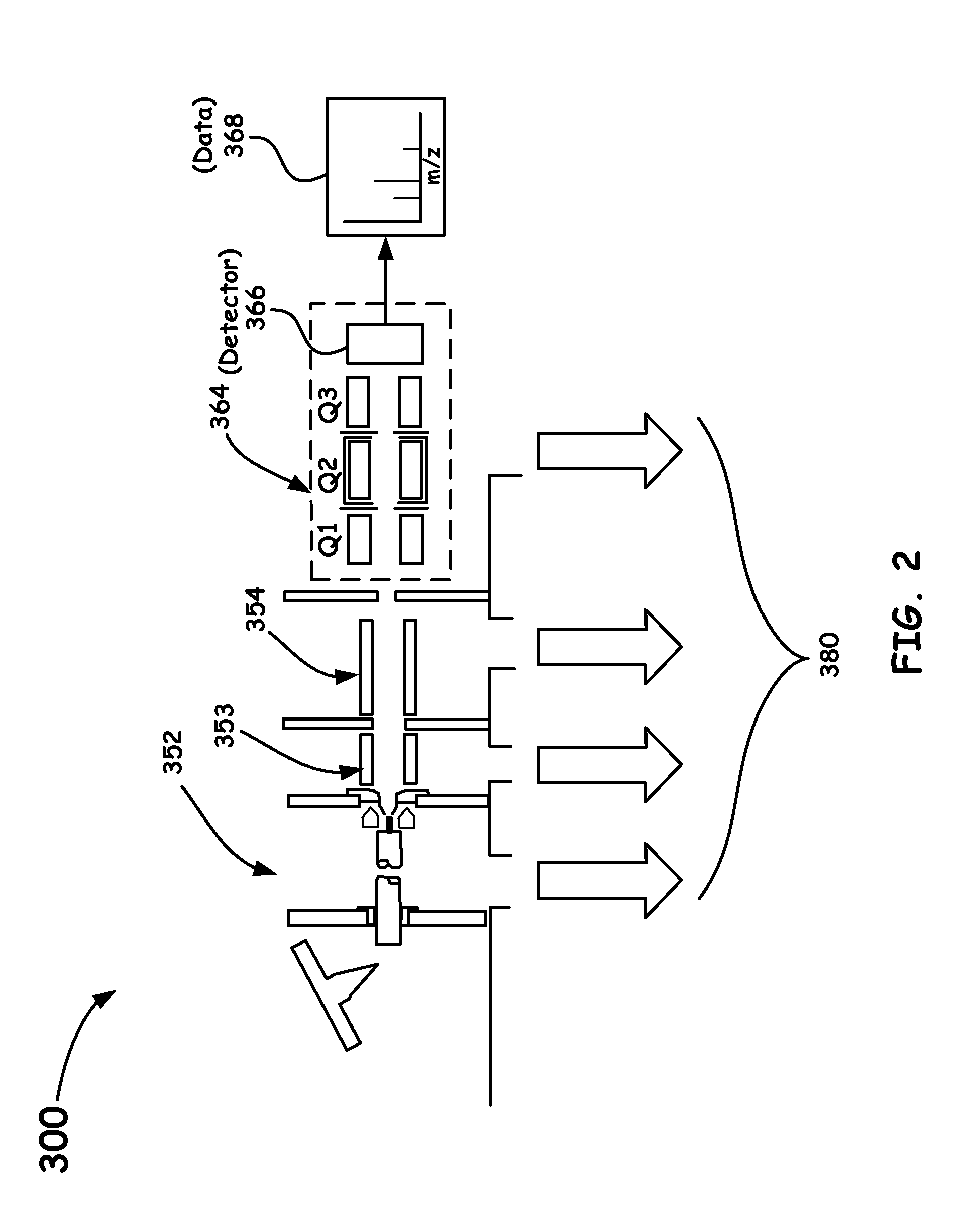
A novel scanning method of a mass spectrometer apparatus is introduced so as to relate by simple time shifts, rather than time dilations, the component signal (“peak”) from each ion even to an arbitrary reference signal produced by a desired homogeneous population of ions. Such a method and system, as introduced herein, is enabled in a novel fashion by scanning exponentially the RF and DC voltages on a quadrupole mass filter versus time while maintaining the RF and DC in constant proportion to each other. In such a novel mode of operation, ion intensity as a function of time is the convolution of a fixed peak shape response with the underlying (unknown) distribution of discrete mass-to-charge ratios (mass spectrum). As a result, the mass distribution can be reconstructed by deconvolution, producing a mass spectrum with enhanced sensitivity and mass resolving power.

Description

BACKGROUND OF THE INVENTION[0001]1. Field of the Invention[0002]The present invention relates to the field of mass spectrometry. More particularly, the present invention relates to a mass spectrometer system and method that provides for an improved mode of operation of a quadrupole mass spectrometer that includes scanning the RF and DC applied fields exponentially versus time while maintaining the RF and DC in constant proportion to each other. In this novel mode of operation, ion intensity as a function of time is the convolution of a fixed peak shape response with the underlying (unknown) distribution of discrete mass-to-charge ratios (mass spectrum). As a result, the mass distribution can be reconstructed by deconvolution, producing a mass spectrum with enhanced sensitivity and mass resolving power.[0003]2. Discussion of the Related Art[0004]Quadrupoles are conventionally described as low-resolution instruments. The theory and operation of conventional quadrupole mass spectromete...

Claims


Application Information

Patent Timeline
IPC IPC(8): H01J49/42H01J49/00G01N27/62
CPCH01J49/429H01J49/4215H01J49/0031H01J49/4225
Inventor GROTHE, JR., ROBERT A.
Owner THERMO FINNIGAN
Learn More