Heat Shield For Improved Continuous Czochralski Process

a technology of czochralski process and heat shield, which is applied in the direction of single crystal growth, polycrystalline material growth, eutectic material solidification, etc., can solve the problems of loss of single silicon structure, serious maintenance problem, dislocation defects

Inactive Publication Date: 2014-05-29
SOLAICX
View PDF3 Cites 10 Cited by
  • Summary
  • Abstract
  • Description
  • Claims
  • Application Information

AI Technical Summary

Benefits of technology

The patent text describes an apparatus and method for growing silicon ingots using the Czochralski method. The apparatus includes a crucible for holding molten silicon and a weir for separating the melted silicon into an inner and outer region. An annular heat shield is placed on top of at least one weir to cover the outer region. The technical effect of this invention is to provide a better control over the temperature and composition of the melt / crystal interface, resulting in improved stability and quality of silicon ingots.

Problems solved by technology

The dust or unmelted silicon particles contaminate the growth region 110 and can become attached to the growing ingot, thereby causing it to lose its single silicon structure.
At silicon process temperatures, silicon oxide formed by dissolution of the quartz crucible evaporates from the melt and condenses on slightly cooler areas of the hot zone to form a powder or dust that may become a serious maintenance problem.
When this powder or dust falls back into the silicon melt it may affect the growing single crystal structure, causing dislocation defects.
Ingot yield and growth economics suffer severely.
Further, the radiative and conductive heat losses require additional heat be added to keep the silicon melted.
Such additional heat adds complexity and cost to the system design.
While this conventional arrangement may be adequate for limiting transmission of un-melted particles of silicon from the melt supplementing region to the crystal growth region, such conventional weir arrangements fail to address the problem of radiative and conductive heat losses to the outside atmosphere.

Method used


Image

  • Heat Shield For Improved Continuous Czochralski Process
  • Heat Shield For Improved Continuous Czochralski Process
  • Heat Shield For Improved Continuous Czochralski Process

Examples


Embodiment Construction

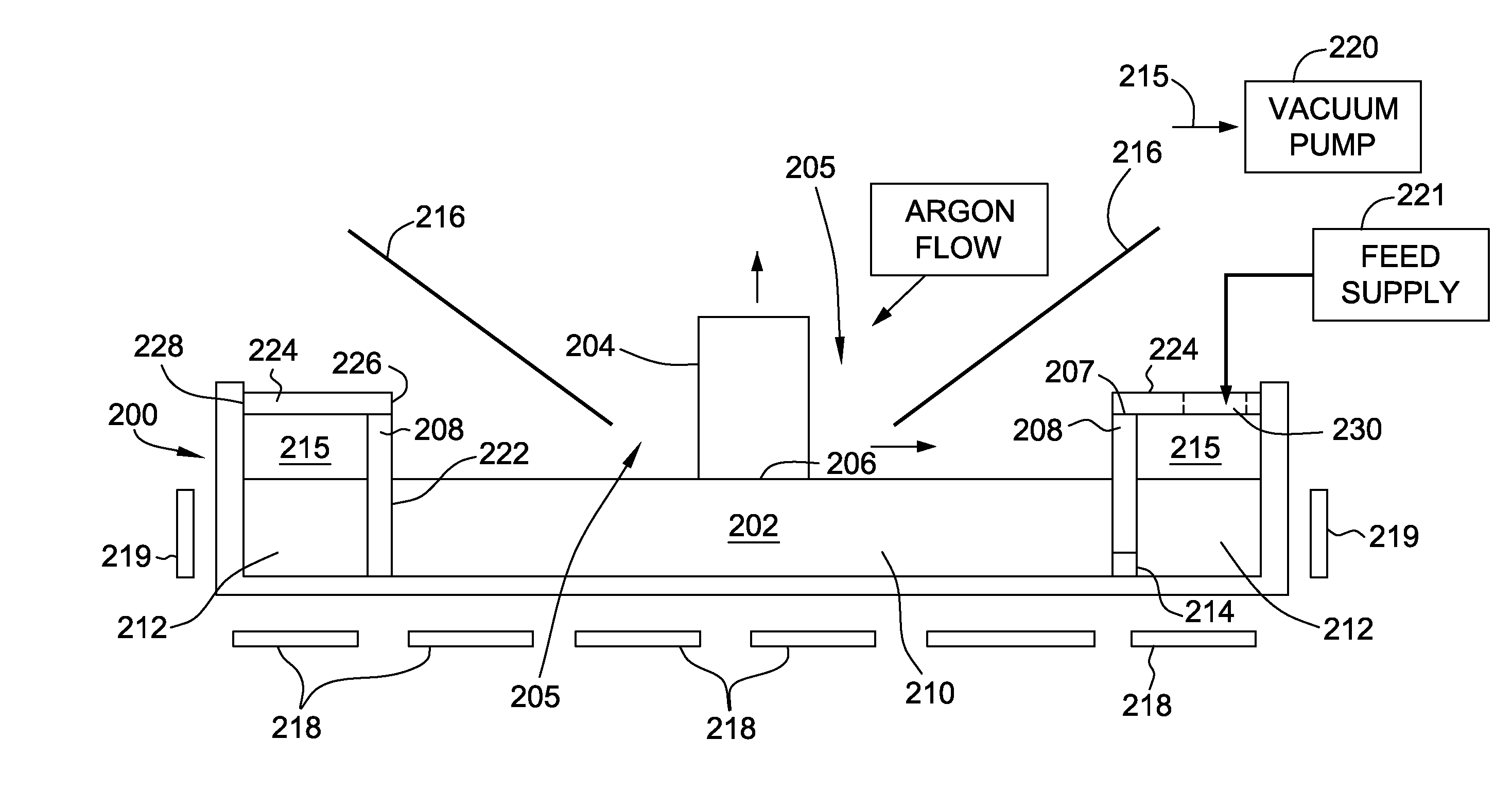
[0016]FIG. 2 shows a schematic diagram of an exemplary embodiment of an apparatus for growing ingots by the Czochralski method. In this embodiment, a weir 208 is provided in a crucible 200 that holds a silicon melt 202. The weir 208 has generally a cylindrical shape with sidewalls 222 supported at the bottom of the crucible that extend upwardly to define the growth region 210 in silicon melt 202. The weir 208 divides the melt into two portions, an inner growth region 210 and an outer, feed supplement region 212. That is, the cylindrical weir separates the growth region 210 from a first region or melt supplement region 212 to substantially isolate and prevent thermal and mechanical perturbations from affecting the growing crystal in the growth region 210. The weir 208 also defines a passageway 214 for providing a controlled melt flow between the melt supplement region 212 and growth region 210. A feed supply 221 supplies a source of solid silicon feedstock, such as chunk or granular ...


PUM

PropertyMeasurementUnit
melting temperatureaaaaaaaaaa
cylindrical shapeaaaaaaaaaa
semiconductoraaaaaaaaaa

Abstract

An apparatus for growing ingots by the Czochralski method is described. The ingots are drawn from a melt / crystal interface in a quantity of molten silicon replenished by crystalline feedstock. The apparatus includes a crucible configured to hold the molten silicon and a weir supported in the crucible. The weir is configured to separate the molten silicon into an inner growth region from an outer region configured to receive the crystalline feedstock. The weir includes a sidewall extending vertically and a top wall. An annular heat shield is disposed on the top wall of the weir that covers at least about 70% of the outer region.

Description

FIELD[0001]The field of the disclosure relates generally to growing crystal semiconductor material by the Czochralski process. More particularly, the field of the disclosure relates to a continuous Czochralski process employing an annular heat shield for improved crystal pulling rates and crucible lifetimes.BACKGROUND[0002]In a continuous Czochralski (CZ) crystal growth process, the melt is supplemented or recharged as the crystal is growing. This is in contrast with batch recharge wherein the melt is recharged after the melt is depleted by a completion of a crystal growing process. In either case the melt can be supplemented either with solid feedstock or molten feedstock.[0003]In contrast to batch recharge, there are advantages of a continuous Czochralski process for growing crystal silicon ingots. The melt height remains substantially constant and therefore the growth conditions at the melt-crystal interface can be maintained more uniformly for optimal crystal growth. The cycle t...

Claims


Application Information

Patent Timeline
Patent Type & Authority Applications(United States)
IPC IPC(8): C30B15/14C30B15/00C30B15/12
CPCC30B15/14C30B15/002C30B15/12Y10T117/1052
Inventor SWAMINATHAN, TIRUMANI N.
Owner SOLAICX
Why Eureka
Try Eureka