
System and method of motion trajectory reconstruction

Inactive Publication Date: 2014-05-15
NAT CENT UNIV
View PDF4 Cites 14 Cited by
  • Summary
  • Abstract
  • Description
  • Claims
  • Application Information

AI Technical Summary

Benefits of technology

The invention provides a system and method for reconstructing the motion of an object using a signal that is analyzed to remove noise. This analysis involves decomposing the signal into different frequencies and selecting the frequency that represents the main action. This helps to improve the accuracy of the trajectory reconstruction and remove unwanted noise.

Problems solved by technology

However, since an original signal recorded by the inertial sensor still contains noise, after the abovementioned numerical integration, the noise is also magnified and accumulated at the same time.
Therefore, if the subsequent coordinate transform is then performed directly, an accumulated shift of an original motion trajectory is caused and the accuracy of the reconstructed motion trajectory is reduced, so that the subsequent research depending on the data is distorted.

Method used


Image

  • System and method of motion trajectory reconstruction
  • System and method of motion trajectory reconstruction
  • System and method of motion trajectory reconstruction

Examples


first embodiment

[0035]As shown in FIG. 3, it is detailed flow chart of the method of motion trajectory reconstruction in the invention.

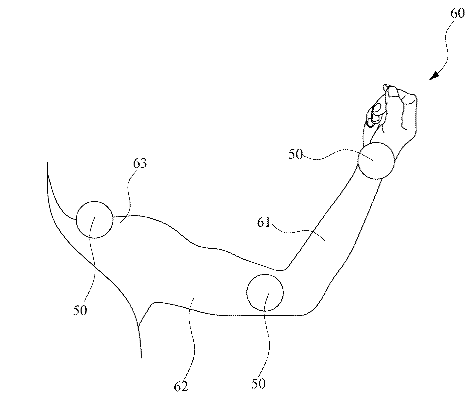
[0036]The inertial sensors 50 are firstly configured before the flow chart starts (referring to FIG. 4). For example, multiple inertial sensors 50 are configured on a fore arm 61, an upper arm 62 and a shoulder 63 of a human arm 60, so that when a convolution motion of the human arm 60 is performed, an inertial sensing signal can be emitted continuously in real time by each of the configured inertial sensors 50. The inertial sensing signal contains linear acceleration data (or referred to as a signal) and angular velocity data (or referred to as a signal). The inertial sensor 50, for example, contains a tri-axial accelerometer and a tri-axial gyroscope. The accelerometer is used for measuring and recording the (linear) acceleration generated in the process of arm motion, and the gyroscope is used for measuring the angular velocity generated in motion.

[0037]In additi...

second embodiment

[0062]As shown in FIG. 6, it is a detailed flow chart of the method of motion trajectory reconstruction in the invention.

[0063]The inertial sensors 50 are firstly configured before the flow chart starts (referring to FIG. 4). Details can be referred to the above description, which are not illustrated any further herein.

[0064]In step 601, the angular velocity time-domain data and the linear acceleration time-domain data fed back by the inertial sensors start to be recorded. In step 602, the spectrum analysis is performed to transform the angular velocity time-domain data into the angular velocity frequency-domain data. Since the steps 601-602 are identical to the steps 301-302 of the first embodiment, these steps are not illustrated any further herein.

[0065]In step 603, the angular velocity frequency-domain data is transformed into the angular displacement frequency-domain data. The difference between the step and the first embodiment is that, the angular velocity frequency-domain da...

third embodiment

[0075]As shown in FIG. 7, it is a detailed flow chart of the method of motion trajectory reconstruction in the invention.

[0076]The third embodiment includes the steps 701-711, wherein in the step 701, the angular velocity time-domain data and the linear acceleration time-domain data fed back by the inertial sensor start to be recorded. In step 702, the spectrum analysis is performed to transform the angular velocity time-domain data into the angular velocity frequency-domain data.

[0077]In step 703, the angular velocity frequency-domain data is filtered. In step 704, the angular displacement time-domain data (i.e., the angular displacement value) is obtained from the filtered angular velocity frequency-domain data.

[0078]In step 705, the transition matrix is calculated from the angular displacement time-domain data. In step 706, the global coordinate linear acceleration time-domain data is calculated from the linear acceleration time-domain data and the transition matrix. In step 707,...


PUM


Abstract

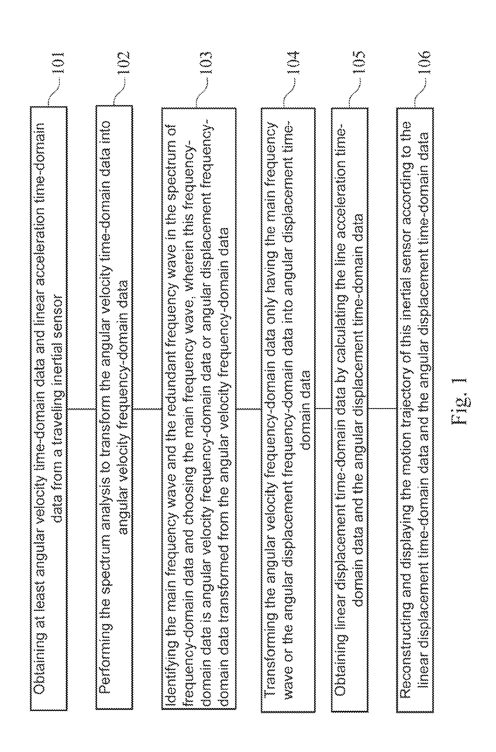
A method of motion trajectory reconstruction is described as follows: obtaining angular velocity time-domain data and linear acceleration time-domain data from a traveling inertial sensor; performing a spectrum analysis to transform the angular velocity time-domain data into angular velocity frequency-domain data; choosing a main frequency wave of the spectrum from the angular velocity frequency-domain data; transforming the angular velocity frequency-domain data only having the main frequency wave into angular displacement time-domain data; obtaining linear displacement time-domain data by calculating the linear acceleration time-domain data and the angular displacement time-domain data; and reconstructing and displaying the motion trajectory of the inertial sensor according to the linear displacement time-domain data and the angular displacement time-domain data.

Description

RELATED APPLICATIONS[0001]This application claims priority to Taiwan Application Serial Number 101142395, filed Nov. 14, 2012, which is herein incorporated by reference.BACKGROUND[0002]1. Field of Invention[0003]The invention relates to a method of motion trajectory reconstruction. particularly, the invention relates to a system and a method of motion trajectory reconstruction based on an inertial sensing signal.[0004]2. Description of Related Art[0005]To contribute to the development of biotechnology health care, human body rehabilitation or even intelligence-beneficial entertainment field, researchers have certain motivation to reconstruct the motion trajectory of human limb for subsequent study. In particularly, the researchers configure an inertial sensor on the human limb. When the human limb moves, displacement data of limb movement can be calculated from the inertial sensing signal (such as a linear acceleration signal and an angular acceleration signal) recorded by the inert...

Claims


Application Information

Patent Timeline
IPC IPC(8): G06F3/03G06F3/01
CPCG06F3/017G06F3/03A61B5/1122
Inventor PAN, MIN-CHUNYANG, CHI-TAIWU, CHAO-MIN
Owner NAT CENT UNIV
Learn More