Robotic Surface Treatment Device

a robotic surface and treatment device technology, applied in the field of robotic surface treatment devices, can solve the problems of ineffective development of a robotic surface cleaning system that can clean any hard surface (e.g. concrete, tiles, vinyl, hardwood, etc., and remains difficult to achieve, and the ability of commercially available, robotic or manual (local or controlled), surface cleaning systems that are commercially available for domestic or industrial surface cleaning applications is extremely limited in comparison to common, hand-held mops, commercially available,

Inactive Publication Date: 2014-05-08
DEMING SYST
View PDF0 Cites 12 Cited by
  • Summary
  • Abstract
  • Description
  • Claims
  • Application Information

AI Technical Summary

Benefits of technology

[0009]At least one treatment fluid tank may be positioned on the top of the robotic surface treatment device. At least one treatment fluid tube may extend from a bottom surface of the treatment fluid tank to a bottom surface of the robotic surface treatment device. The plurality of sensors may be laser or acoustic sensors configured to measure a distance between the robotic surface treatment device and an obstacle. The sensors may be spaced radially about the robotic surface treatment device and may be positioned with equal distances between one another. A treatment fluid tube shut off valve may be positioned in line between the treatment fluid tank and the treatment fluid tube, wherein the treatment fluid tube shut off valve opens upon the robotic surface treatment device activating to treat a surface. The rechargeable battery may be a light weight lithium ion battery. The treatment pads may include an abrasive material configured to scrub, polish, buff, and / or clean a hard surface. Alarms and status indicators may be integrated into the main controller to alert an individual that the rechargeable battery power level is low, that the treatment fluid level is low, and / or that the electric motors have stalled or powered down. The plurality of sensors may be positioned at an angle of approximately 22 degrees apart from one another. The electric motors used to rotate the wheels may be servo motors or stepper motors. At least one weight may be provided on a top surface of the robotic surface treatment device, wherein a rod may be positioned on a top surface of the robotic surface treatment device and the at least one weight may be positioned on the rod. The robotic surface treatment device may be operated through the use of a remote control device.
[0010]In another embodiment of the invention, a method of treating a surface using a robotic surface treatment device includes the steps of: providing a robotic surface treatment device as described hereinabove, rotating the wheels of the robotic surface treatment device via rotation of the motor shafts, wherein the motor shafts may be rotated by the electric motors, and increasing the rotational speed of a first wheel comparative to a second wheel, thereby moving the first wheel along a radial trajectory line until the first wheel is positioned in front of the second wheel, wherein the first wheel may be initially positioned at the back of the robotic surface treatment device and the second wheel may be initially positioned at the front of the robotic surface treatment device.
[0011]The method may further include the step of using the main controller to create a boundary line of the treating area by using the sensors to determine the distance and coordinates of the treating area. The method may further include the step of recalculating the boundary line of the treating area by using the sensors of the main controller to re-calibrate the distance and coordinates of the treating area. The method may further include the step of walking the robotic surface treatment device along a treating path by repeating the steps described hereinabove at least two times, wherein the wheels may be rotated in an opposite direction after the first wheel has been brought to the front of the robotic surface treatment device. The method may further include the step of treating a circular area by rotating one wheel at one rotational speed and rotation the other wheel at a comparatively faster speed in the same rotational direction. The method may further include the step of providing a treatment fluid in at least one treatment fluid tank positioned on top of the robotic surface treatment device, and at least one treatment fluid tube that may extend from the treatment fluid tank to a bottom surface of the robotic surface treatment device. The method may further include the step of spreading treatment fluid on the treating area and the treatment pads via the treatment fluid tube. The method may further include the step of remotely operating the robotic surface treatment device via a remote control device.
[0012]These and other features and characteristics of the robotic surface treatment device, as well as the methods and functions of the related elements of the robotic surface treatment device, will become more apparent upon consideration of the following description and the appended claims with reference to the accompanying drawings, all of which form a part of this specification, wherein like reference numerals designate corresponding parts in the various figures. It is to be expressly understood, however, that the drawings are for the purpose of illustration and description only and are not intended as a definition of the limits of the invention. As used in the specification and the claims, the singular form of “a”, “an”, and “the” include plural referents unless the context clearly dictates otherwise.

Problems solved by technology

Development of an effective robotic surface cleaning system that can clean any hard surface (e.g. concrete, tiles, vinyl, hardwood, or any combination of these materials) remains difficult to achieve.
The state-of-the-art autonomous or tele-operated, robotic or manual (local or controlled) surface cleaning systems that are commercially available for domestic or industrial surface cleaning applications are still ineffective in comparison to common, hand-held mops.
These commercially available, wheeled, surface cleaning systems are extremely limited in their ability to properly clean a surface.
These systems are incapable of rubbing or pushing the cleaning tools of the system (a cloth or brush) with the requisite amount of pressure necessary for removing dirt, grease, mud, or any other substance from a hard surface.

Method used


Image

  • Robotic Surface Treatment Device
  • Robotic Surface Treatment Device
  • Robotic Surface Treatment Device

Examples


Embodiment Construction

[0029]For purposes of the description hereinafter, the terms “upper”, “lower”, “right”, “left”, “vertical”, “horizontal”, “top”, “bottom”, “lateral”, “longitudinal”, and derivatives thereof shall relate to the invention as it is oriented in the drawings. However, it is to be understood that the invention may assume alternative variations and step sequences, except where expressly specified to the contrary. It is also to be understood that the specific devices and processes illustrated in the attached drawings, and described in the following specification, are simply exemplary embodiments of the invention. Hence, specific dimensions and other physical characteristics related to the embodiments disclosed herein are not to be considered as limiting.

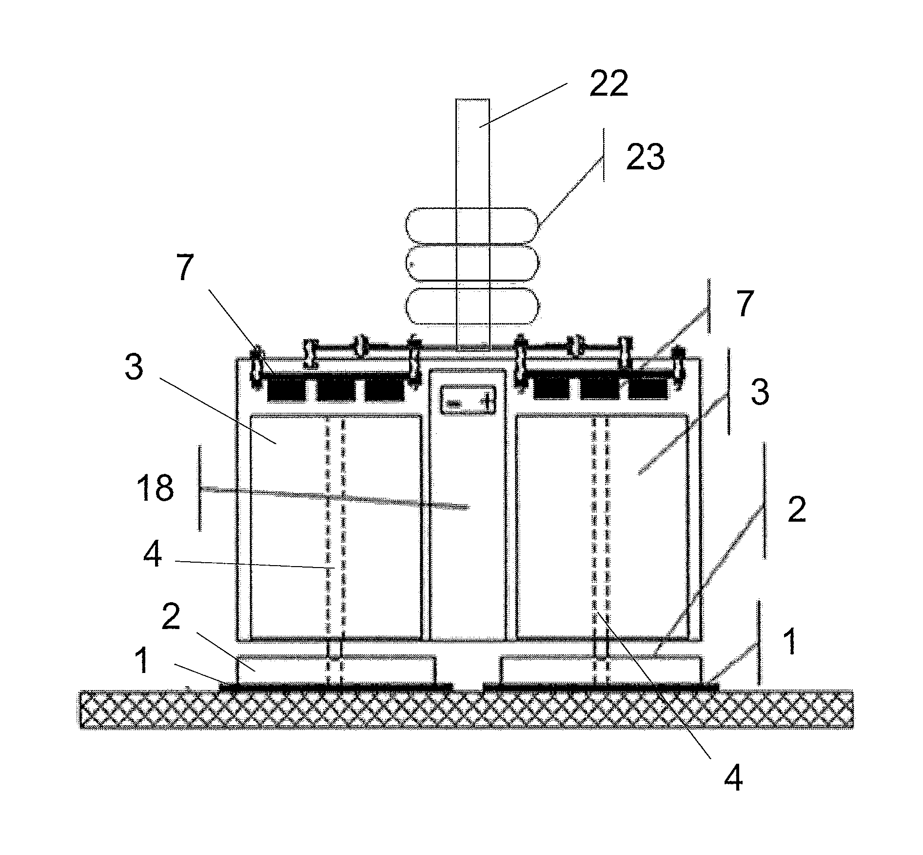
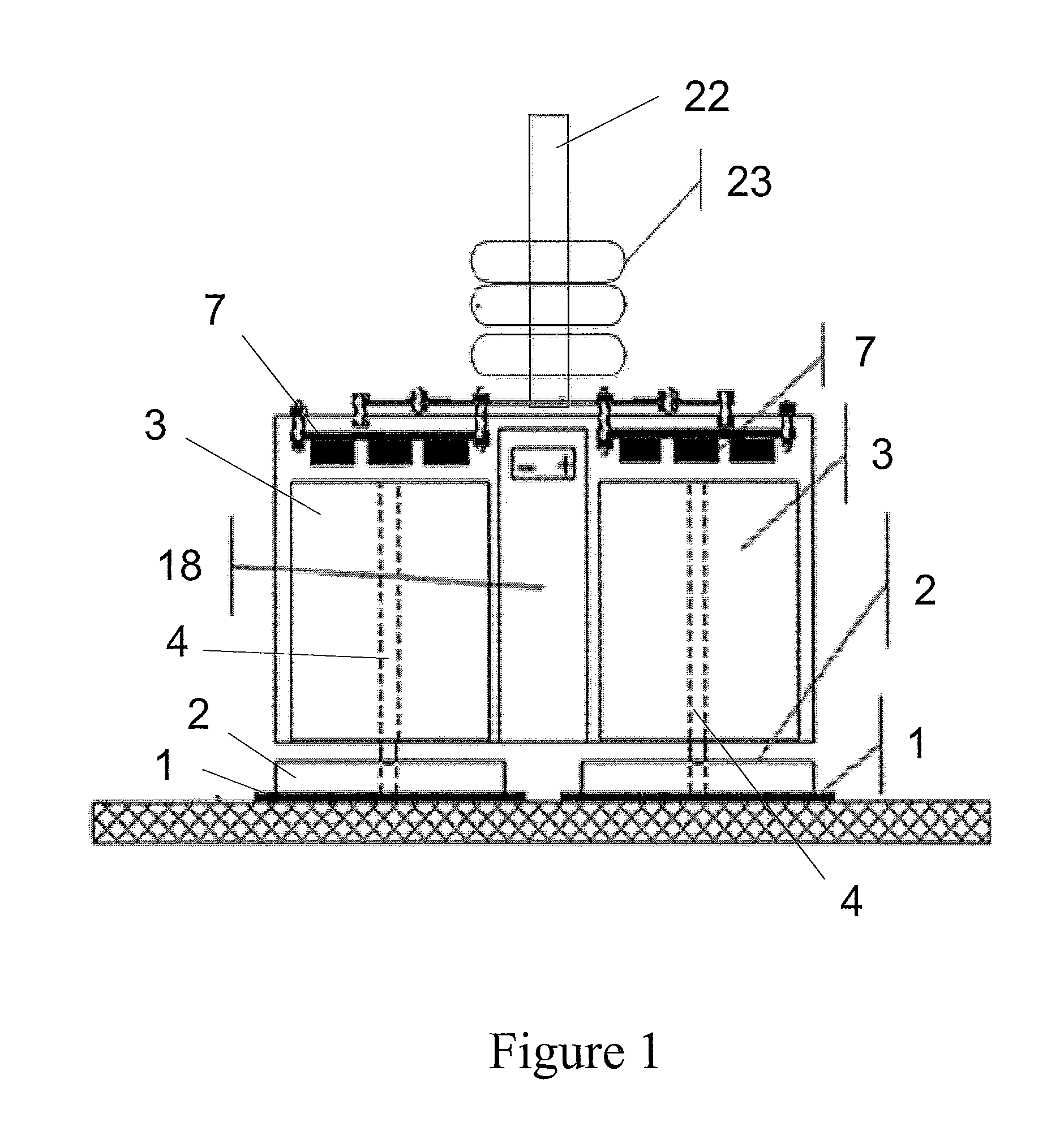
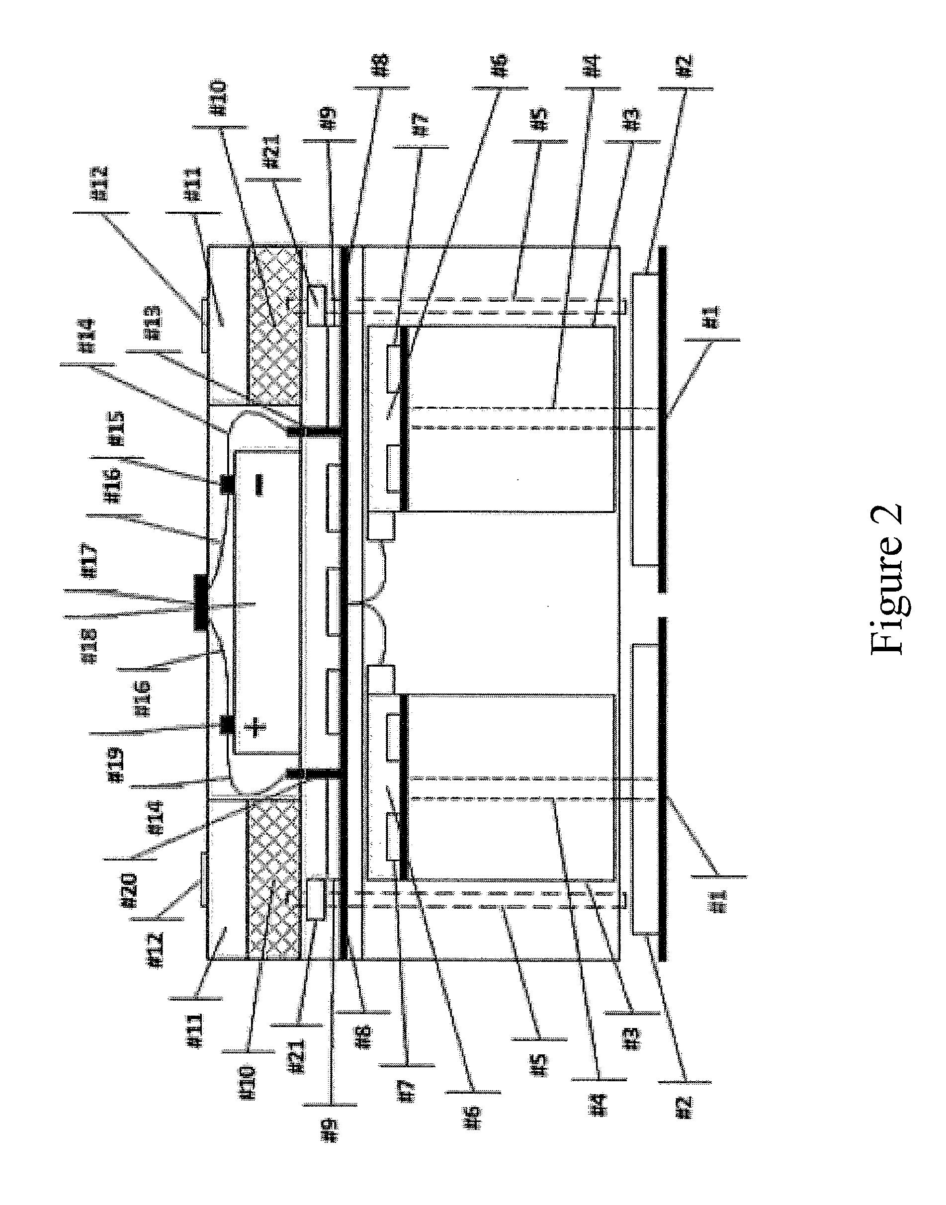
[0030]The present invention is directed to, in general, a robotic surface treatment device and, in particular, a robotic surface treatment device with floor pads rotationally actuated to treat a surface. Certain preferred and non-limiting em...


PUM

PropertyMeasurementUnit
angleaaaaaaaaaa
angleaaaaaaaaaa
angleaaaaaaaaaa

Abstract

A robotic surface treatment device includes at least two wheels, at least two electric motors, wherein one electric motor is connected to one corresponding wheel via a motor shaft, at least two treatment pads, wherein at least one treatment pad is attached to a bottom surface of a corresponding wheel, a main controller positioned on top of and in connection with drive controllers positioned on top of each electric motor, a plurality of sensors integrated in the main controller, and a rechargeable battery connected to the main controller. At least one treatment fluid tank may be positioned on the robotic surface treatment device, and at least one treatment fluid tube may extend from a bottom surface of the treatment fluid tank to a bottom surface of the robotic surface treatment device. The sensors may be laser or acoustic sensors configured to create a boundary line for a treatment area.

Description

CROSS REFERENCE TO RELATED APPLICATIONS[0001]This application claims the benefit of U.S. Provisional Application No. 61 / 722,183, filed Nov. 4, 2012, the disclosure of which is hereby incorporated in its entirety by reference.BACKGROUND OF THE INVENTION[0002]1. Field of the Invention[0003]This disclosure relates generally to a robotic surface treatment device and, more particularly, to a robotic surface treatment device with floor pads rotationally actuated to treat a surface.[0004]2. Description of Related Art[0005]Development of an effective robotic surface cleaning system that can clean any hard surface (e.g. concrete, tiles, vinyl, hardwood, or any combination of these materials) remains difficult to achieve. The state-of-the-art autonomous or tele-operated, robotic or manual (local or controlled) surface cleaning systems that are commercially available for domestic or industrial surface cleaning applications are still ineffective in comparison to common, hand-held mops. These co...

Claims


Application Information

Patent Timeline
Patent Type & Authority Applications(United States)
IPC IPC(8): B24B1/00B24B7/00
CPCB24B7/005B24B1/00A47L11/16A47L11/4005A47L2201/022A47L2201/04
Inventor ROY, UDAY S.SHETH, VISHAL P.ROY, PRITHWI S.SAHA, SHIBANIROY, MOHAR
Owner DEMING SYST
Why Eureka
Try Eureka