
Method and device for determining a temperature of a sheathed-element glow plug during operation in an internal combustion engine

a technology of glow plugs and temperature, which is applied in the direction of machines/engines, instruments, heat measurement, etc., can solve the problems of reducing the measurement set-up at the sheathed-element glow plugs, hammering the application of the control unit for the installed sheathed-element glow plugs, etc., to achieve better starting performance, reduce the tolerance range of maximum permissible temperature, and the effect of higher maximum temperatur

Active Publication Date: 2014-05-08
ROBERT BOSCH GMBH
View PDF2 Cites 2 Cited by
  • Summary
  • Abstract
  • Description
  • Claims
  • Application Information

AI Technical Summary

Benefits of technology

The present invention is about a method for controlling a sheathed-element glow plug in an internal combustion engine. After installation, a calibration step is carried out to determine the specific temperature-resistance correlation of the glow plug during operation. This allows for a higher maximum temperature in the control unit, leading to better starting performance, quieter idling, and reduced emissions. The processing unit applies a first and second voltage to the glow plug, and the current sensor sends signals to the processing unit which are used to determine the temperature-resistance correlation. This cost-effective method ensures reliable control of the glow plug and accurate determination of its operating temperature.

Problems solved by technology

This hampers the application of the control unit for the installed sheathed-element glow plug, since great tolerances are considered during use of the sheathed-element glow plug in the internal combustion engine.
The actual temperature of the sheathed-element glow plug is thereby ascertained without direct temperature measurement, which reduces the measurement set-up at the sheathed-element glow plugs.

Method used


Image

  • Method and device for determining a temperature of a sheathed-element glow plug during operation in an internal combustion engine
  • Method and device for determining a temperature of a sheathed-element glow plug during operation in an internal combustion engine
  • Method and device for determining a temperature of a sheathed-element glow plug during operation in an internal combustion engine

Examples


Embodiment Construction

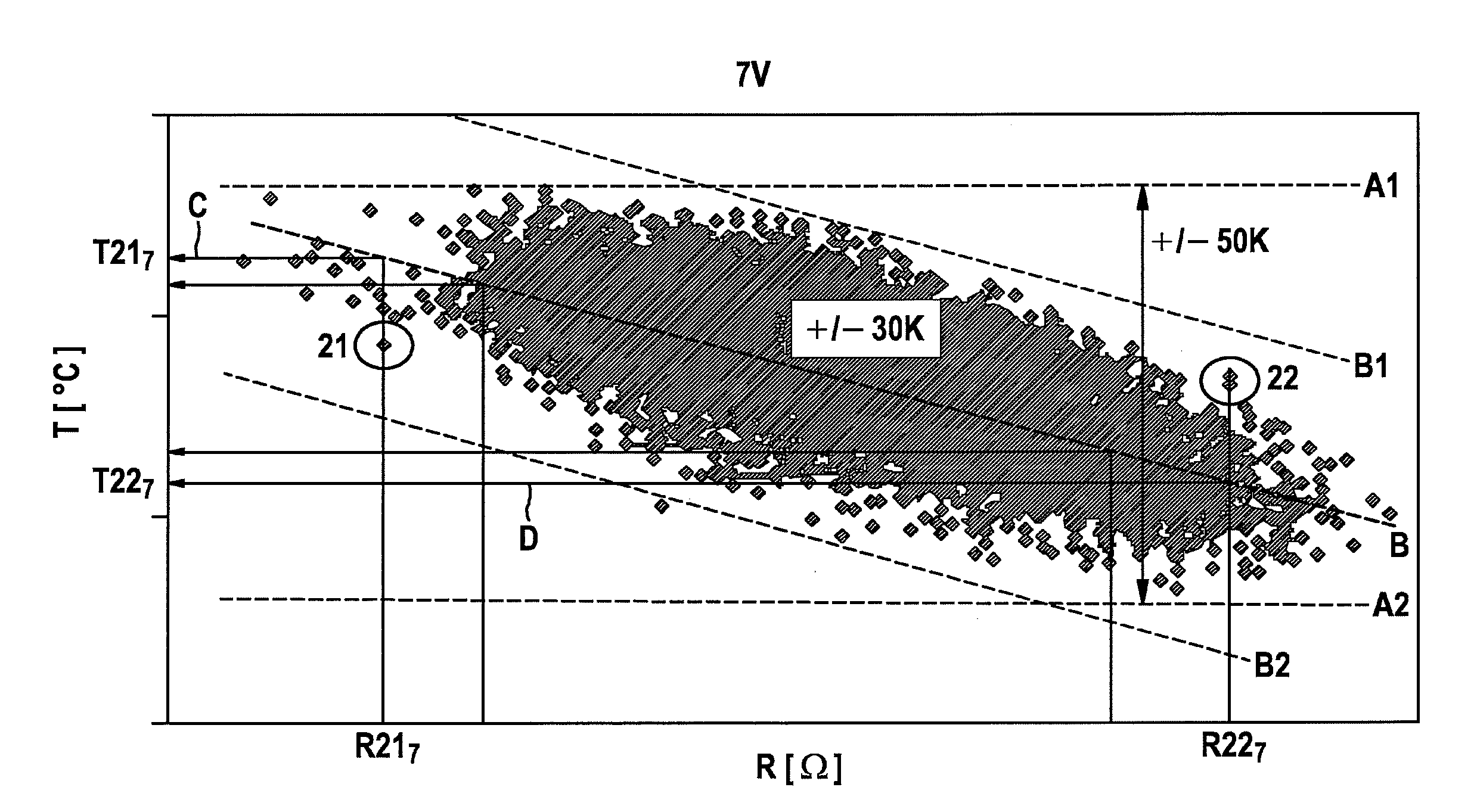
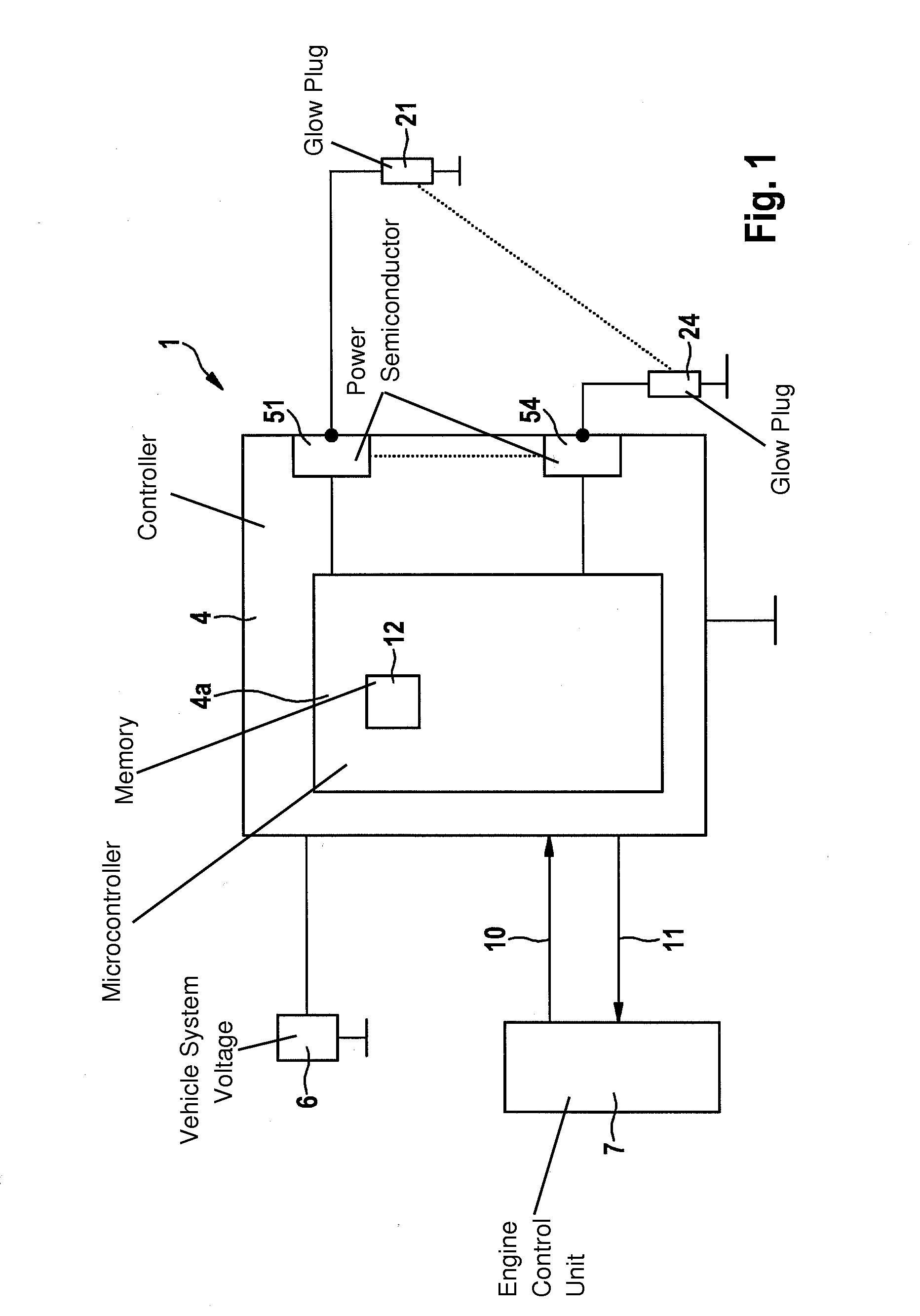
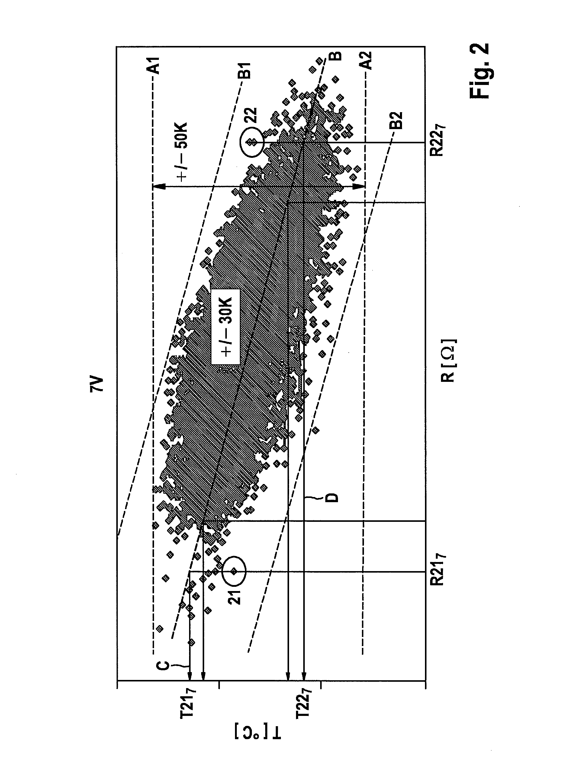
[0023]At ambient temperatures of <40° C., cold combustion engines, especially diesel engines, need a starting aid to ignite the fuel / air mixture fed into the internal combustion engine. Glow systems are used as starting aid, which are made up of sheathed-element glow plugs, a glow-time controller and glow software which is stored in an engine control unit or the glow-time controller. In addition, glow systems are also used to improve the emissions of the vehicle. Further application areas of the glow system lie in the burner exhaust system, the auxiliary heater, the preheating of fuel or the preheating of the coolant.

[0024]FIG. 1 shows such a glow system, in which a plurality of sheathed-element glow plugs 21 through 24 are present, each sheathed-element glow plug 21 through 24 extending into a respective cylinder (not further shown) of a combustion chamber of the internal combustion engine. Sheathed-element glow plugs 21 through 24 are identical and represent customary low-voltage ...


PUM


Abstract

A method for determining the temperature of a sheathed-element glow plug during operation in an internal combustion engine is described, in which a temperature-resistance reference correlation is determined. In order to reduce the tolerance range of a sheathed-element glow plug, after the sheathed-element glow plug has been installed in the internal combustion engine, a calibration step is carried out in which, with the aid of the temperature-resistance reference correlation determined prior to the installation of the sheathed-element glow plug in the internal combustion engine, a temperature-resistance correlation specific to the sheathed-element glow plug is ascertained, from which the temperature of the sheathed-element glow plug during operation of the sheathed-element glow plug in the internal combustion engine is determined.

Description

FIELD OF THE INVENTION[0001]The present invention relates to a method for determining the temperature of a sheathed-element glow plug during operation in an internal combustion engine, whereby a temperature-resistance reference correlation is determined, as well as a device for carrying out the method.BACKGROUND INFORMATION[0002]From the standpoint of production engineering, sheathed-element glow plugs which are used in an internal combustion engine have a predefined tolerance of the temperature to be set at the sheathed-element glow plug for a nominal voltage. Thus, for example, for a ceramic sheathed-element glow plug, given a nominal voltage of 7 volts with which the sheathed-element glow plug is activated, a temperature of 1,200° C. is indicated as glow temperature, which allows a tolerance of + / −50 K. This means that the maximum temperature of the sheathed-element glow plug is not allowed to exceed 1,250° C. If control units which activate the sheathed-element glow plugs in the...

Claims


Application Information

Patent Timeline
IPC IPC(8): G01K15/00
CPCG01K15/005F02P19/023F02P19/025
Inventor KAPPELMANN, PETER
Owner ROBERT BOSCH GMBH
Learn More