Shower door pulley device

Inactive Publication Date: 2014-05-01
FOSHAN IDEAL
View PDF6 Cites 7 Cited by
  • Summary
  • Abstract
  • Description
  • Claims
  • Application Information

AI Technical Summary

Benefits of technology

The invention is a pulley device for shower doors that prevents the door from hitting the shower wall or jumping upward unexpectedly. It uses an elastic member that pushes down on the pulley bracket, ensuring that the pulleys stay in place and prevent the door from moving. This reduces vibration and makes assembly and disassembly easier. A decorative cover can also be added for a more aesthetic appearance. Overall, the invention improves the functionality and appearance of shower doors.

Problems solved by technology

However, the pulley device will be easy to jump, or even derail when the shower door is impacted by external force or suddenly locked.
In particular, a movable glass door may get cracked when detached from the rail, possibly making people injured and bringing a big potential safety problem.
Meanwhile, it entails a lot of time and effort to reinstall the movable door derailed from the rail so that it is inconvenient to be used.

Method used


Image

  • Shower door pulley device
  • Shower door pulley device
  • Shower door pulley device

Examples


example 1

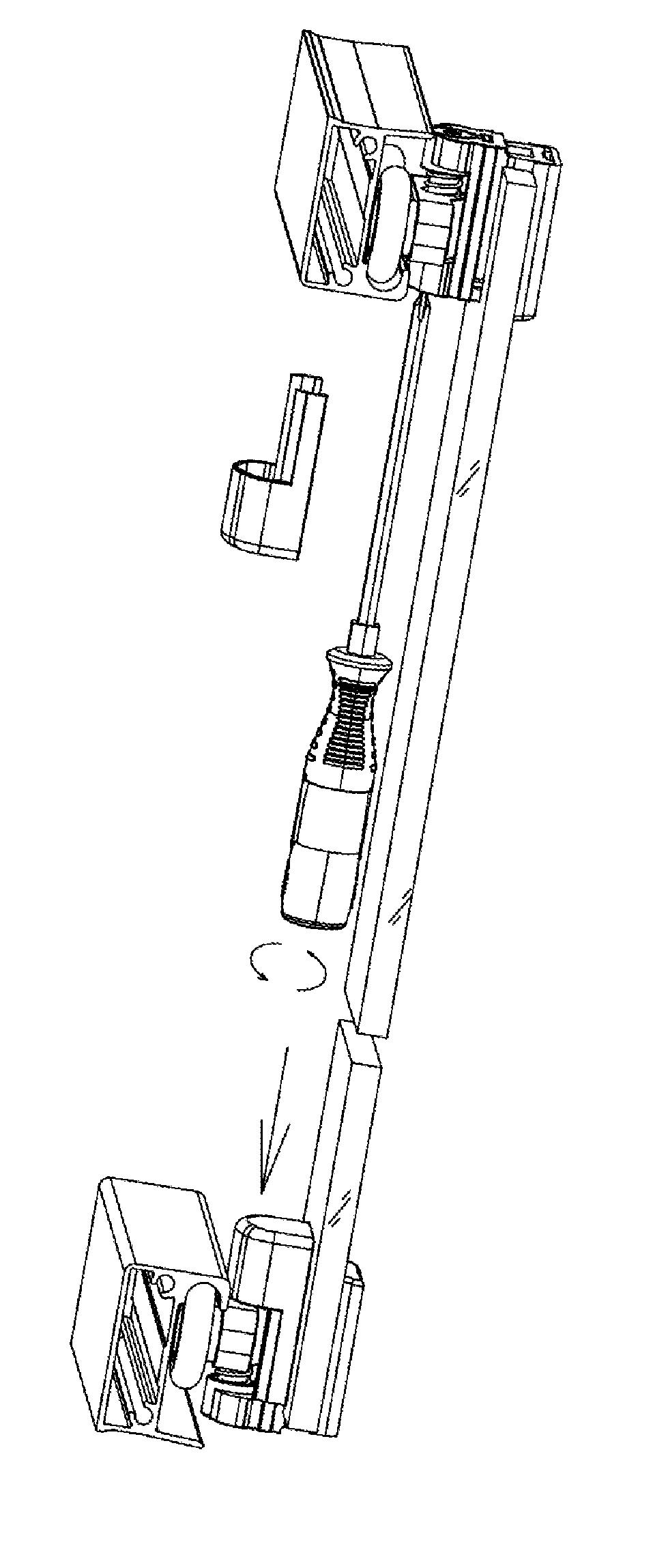
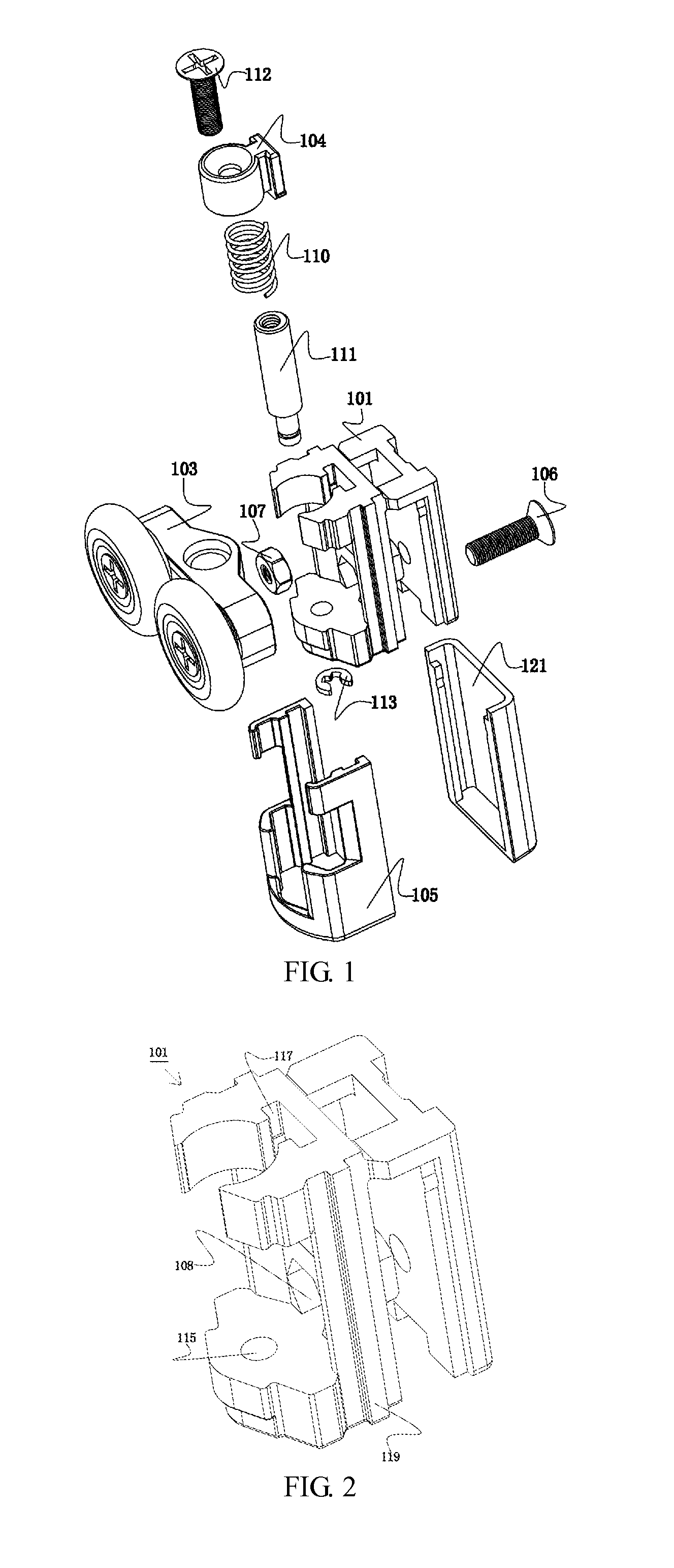
[0044]Referring to FIGS. 1 to 5, a pulley device 100 used for shower doors is shown which comprises a pulley seat 101 attached to a movable door; a pulley bracket 103 having at least one pulley 102 and an elastic member; a pressing block 104 to press said elastic member and slidable relative to the pulley seat 101; a sliding cover 105 slidablely mounted on said pulley seat 101, supporting the pulley bracket 103.

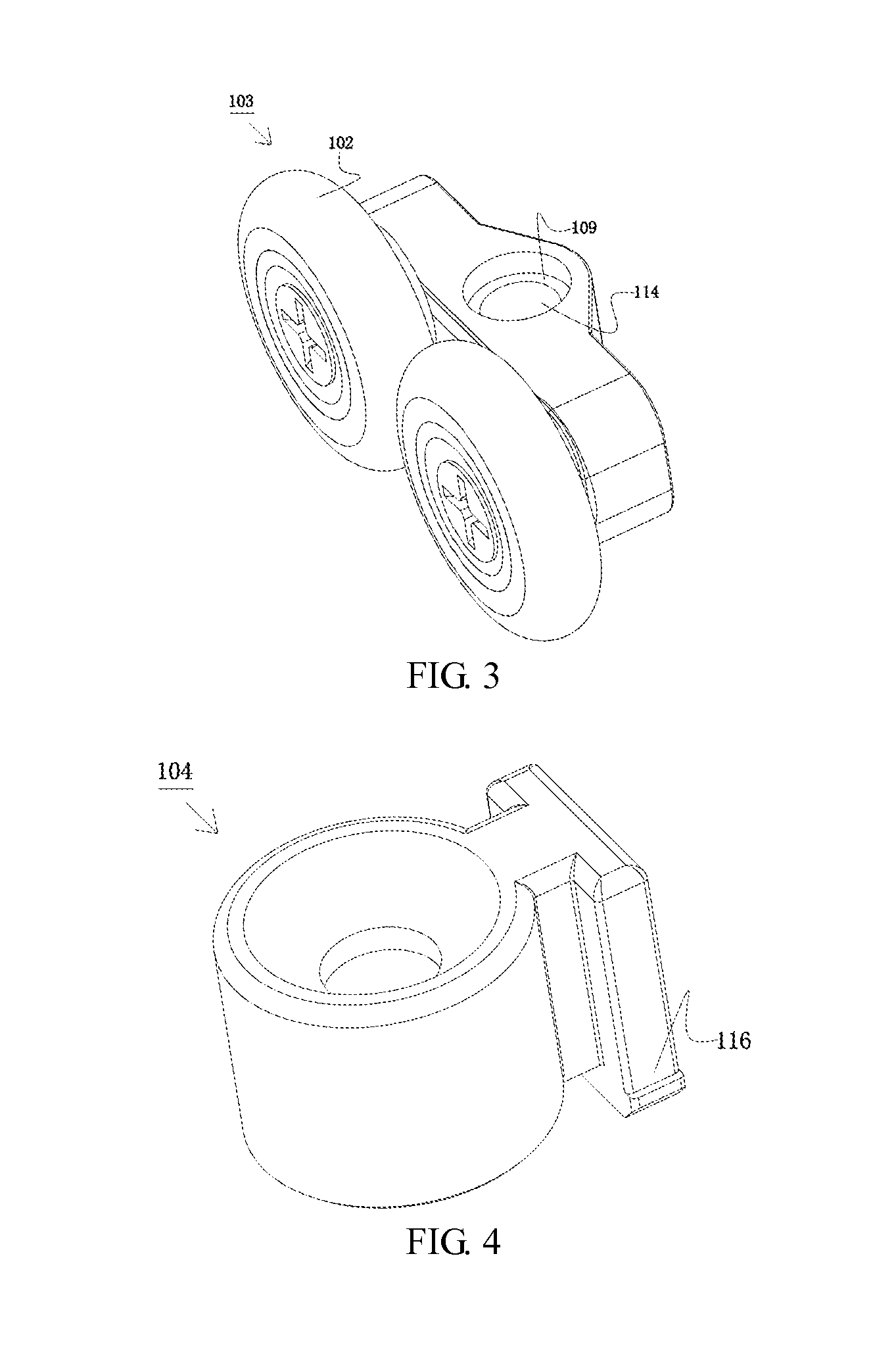
[0045]As shown in FIGS. 1 and 2, the pulley seat 101 is mounted on the movable door by a screw 106 and a nut 107 so that it is convenient for assembly and disassembly and able to guarantee a tight, safe and long-term connection. In the present example, the nut 107 is hexagonal and placed into a hexagonal hole 108 formed on the pulley seat 101, to make sure that it does not rotate and move during connection with the screw 106.

[0046]As shown in FIGS. 1 and 3, a recess 109 is provided on the pulley bracket 103 to receive said elastic member, with one end of the elastic member pl...

example 2

[0055]As shown in FIGS. 13 to 19, the present example is substantively equal to example 1 except that the connecting means comprises a screw 122. A connecting shaft 124 with a screw hole 123 is formed on the pressing block 104. The connecting shaft 124 is passed through the spring 110 and then the through hole 114 of the pulley bracket 103, and the screw 122 is passed through the through hole 115 of the pulley seat 101 and screwed together with the screw hole 123 of the connecting shaft 124. The pulley bracket 103 can rotate and slide up and down with respect to the connecting shaft 124. The spring 110 is pressed by the pressing block 104. Meanwhile, the slider 116 on the pressing block 104 slides into the groove 117 on the pulley seat 101 and can slide up and down with respect to the groove 117.

[0056]As shown in FIGS. 14 and 16, a bulge 125 is provided on the pulley seat 101 and the sliding cover 105 respectively, abutting against with each other to make sure that the sliding cover...


PUM


Abstract

A shower door pulley device is provided which comprises a pulley seat installed on a movable door; a pulley bracket having at least one pulley and an elastic member; a pressing block to press said elastic member and slidable relative to the pulley seat; a sliding cover slidablely mounted on said pulley seat, supporting the pulley bracket.

Description

CROSS-REFERENCE TO RELATED APPLICATIONS[0001]The present application claims the benefit of Chinese utility model application No. 201220570372.4 filed on 1 Nov. 2012, the disclosure of which is incorporated herein by reference.FIELD OF THE INVENTION[0002]The present invention relates to a shower door and, in particular, to a pulley device used for shower doors, having functions of preventing derailment and reducing vibration.BACKGROUND OF THE INVENTION[0003]Shower doors of the state of the art comprise a movable door and a rail. A pulley device is attached to the movable door, sliding within the rail in order to open or close the movable door. However, the pulley device will be easy to jump, or even derail when the shower door is impacted by external force or suddenly locked. In particular, a movable glass door may get cracked when detached from the rail, possibly making people injured and bringing a big potential safety problem. Meanwhile, it entails a lot of time and effort to rein...

Claims


Application Information

Patent Timeline
IPC IPC(8): E05D13/00E05F11/54
CPCE05D13/00E05F11/54E05D15/063E05Y2900/114E05Y2201/688
Inventor WEI, WUXIANG
Owner FOSHAN IDEAL
Why Eureka
Try Eureka