
Arrangement for cooling subassemblies of an automation or control system

a technology of automation or control system and arrangement of cooling subassemblies, which is applied in the direction of cooling/ventilation/heating modifications, printed circuit details, printed circuits, etc., can solve the problems of destroying adjacent temperature-sensitive components such as memory modules, affecting the useful life of devices, and affecting the service life of devices, so as to keep waste heat and dissipate waste heat from the printed circuit board

Active Publication Date: 2014-04-24
ABB (SCHWEIZ) AG
View PDF17 Cites 4 Cited by
  • Summary
  • Abstract
  • Description
  • Claims
  • Application Information

AI Technical Summary

Benefits of technology

The patent describes a way to cool down different parts of an automation or control system that are used outdoors. These parts can include central units, communication modules, and input / output units, among others. The cooling is done by using heat sinks that help to dissipate the heat that accumulates over these components. The invention can help to prevent overheating that could damage the system, and it can also help to keep it running at optimal performance.

Problems solved by technology

The operation of the subassemblies can lead to heating of the subassembly or of the components arranged thereon as a result of the power loss of the components arranged thereon through which current flows.
For example, during their operation, processors can develop waste heat, which can destroy adjacent temperature-sensitive components such as memory modules.
For control systems which can be used under different climatic conditions, these measures may not be sufficient to provide a useful service life of the device, or prevent the operation of components in undesirable environmental temperature ranges.
In addition, for example, the mounting of fans cannot always be achieved in a suitable manner to cool the device.

Method used


Image

  • Arrangement for cooling subassemblies of an automation or control system
  • Arrangement for cooling subassemblies of an automation or control system

Examples


Embodiment Construction

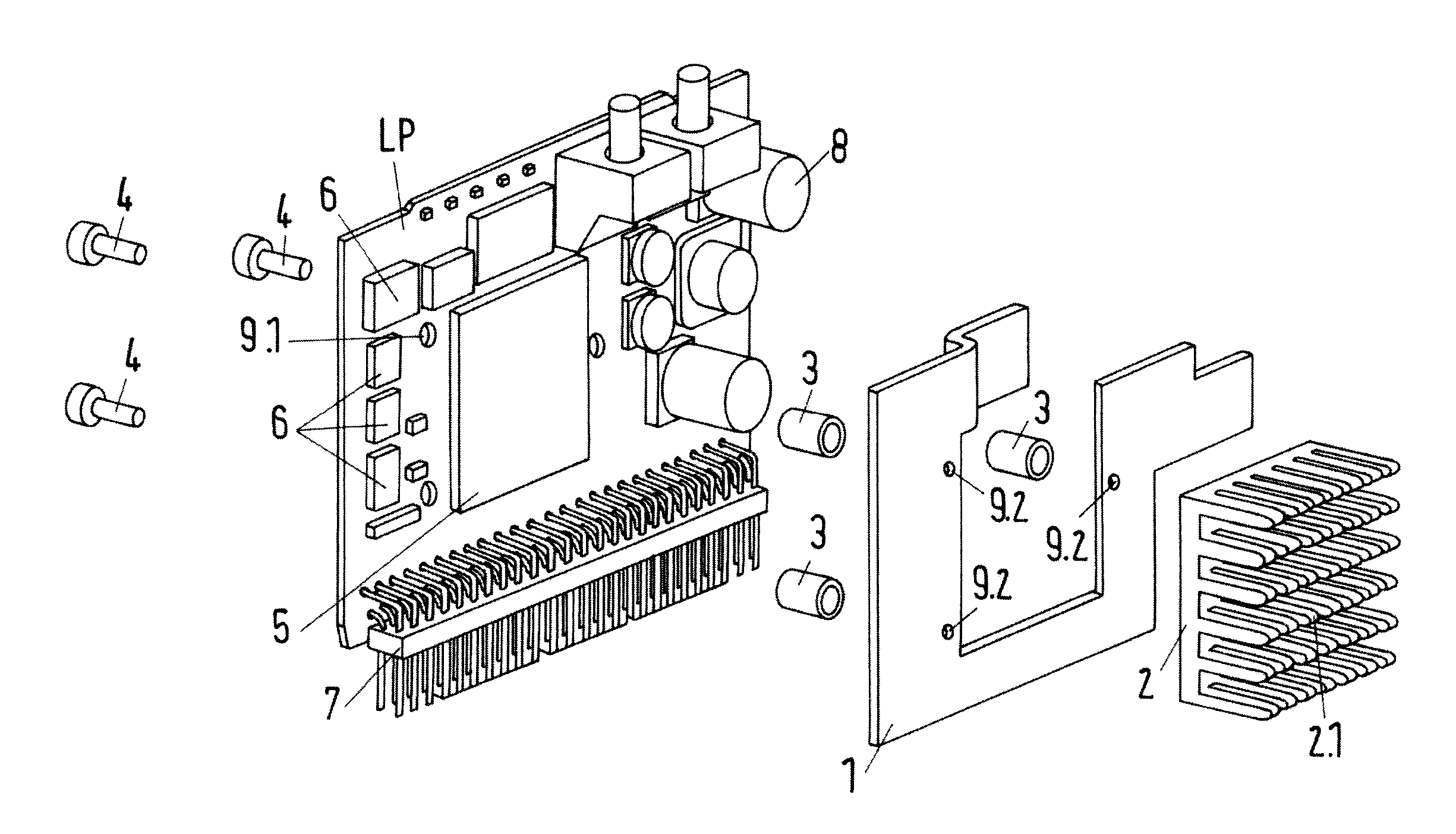
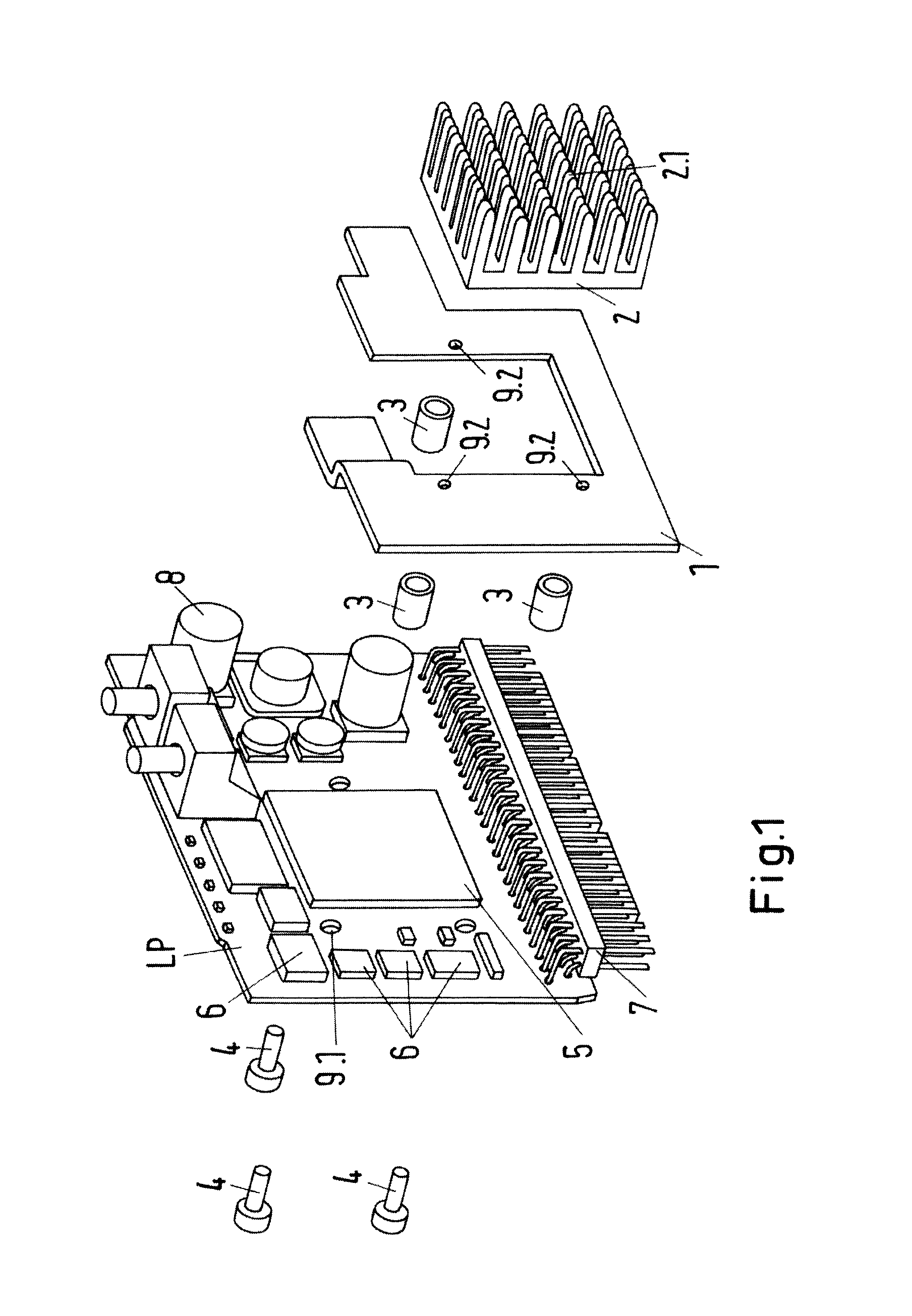
[0013]In accordance with an exemplary embodiment, an arrangement for cooling subassemblies of an automation or control system is disclosed, for example, one suitable for outdoor use, which can take into account the different amounts of waste heat from the various types of electronic components arranged on a printed circuit board and can protect temperature-sensitive components against the waste heat from other components, in order to avoid failure or destruction of the subassemblies, for example, under various climatic conditions. The arrangement according to the disclosure for cooling subassemblies can use standard components in the subassemblies of an automation or control system operating under climatic conditions and can avoid the use of costly temperature-insensitive components.

[0014]In accordance with an exemplary embodiment, an arrangement for cooling subassemblies of an automation or control system is disclosed, which can be suitable for subassemblies which can be used for c...


PUM


Abstract

An arrangement for cooling subassemblies of an automation or control system is disclosed, wherein the subassemblies each comprise at least one printed circuit board (LP) having electronic components of different temperature sensitivity arranged thereon. The printed circuit board (LP) has at least one first portion for temperature-sensitive components and at least one second portion for temperature-insensitive components that generate waste heat. Interspaces are arranged between the first portion and the second portion, the interspaces each forming a thermally insulated trench. Means can be provided which keep away the heat over the temperature-sensitive components in a suitable manner and dissipate the waste heat from the printed circuit board (LP) before the heat reaches the temperature-sensitive components.

Description

RELATED APPLICATION(S)[0001]This application claims priority as a continuation application under 35 U.S.C. §120 to PCT / EP2012 / 002825, which was filed as an International Application on Jul. 5, 2012, designating the U.S., and which claims priority to German Application No. 10 2011 107 316.0 filed on Jul. 6, 2011. The entire content of these applications are hereby incorporated by reference in their entireties.FIELD[0002]The disclosure relates to an arrangement for cooling subassemblies of an automation or control system, which can be used for controlling and / or monitoring outdoor installations, such as a wind power plant.BACKGROUND INFORMATION[0003]Automation systems for controlling an industrial process can include a multiplicity of subassemblies or devices, for example, which can include a central control unit, also called a central unit, communications modules and input / output units.[0004]The subassemblies of an automation system as described in EP 2187279 A1, for example, can be ...

Claims


Application Information

Patent Timeline
Patent Type & Authority Applications(United States)
IPC IPC(8): H05K1/02
CPCH05K1/021H05K1/0201H05K1/0203H05K2201/062H05K2201/09063H05K2201/09972
Inventor GUTERMUTH, STEFAN
Owner ABB (SCHWEIZ) AG
Learn More