
Intensifier

a technology of inverter and airflow rate, which is applied in the field of inverter, can solve the problems of insufficient air flow rate, damage to one or more components in the rack, and failure of one or more rack components, etc., and achieves the effect of discharging waste heat, reducing heat loss, and increasing air flow ra

Inactive Publication Date: 2006-09-07
HEWLETT PACKARD DEV CO LP
View PDF7 Cites 28 Cited by
  • Summary
  • Abstract
  • Description
  • Claims
  • Application Information

AI Technical Summary

Benefits of technology

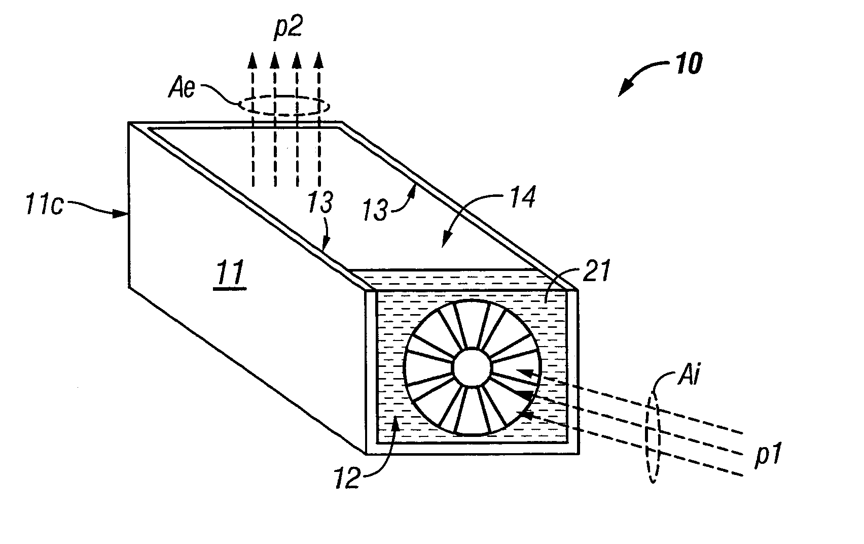
[0009] The intensifier solves the aforementioned problems because the ambient that exits the exhaust port at the second pressure generates a higher air flow rate out of the exhaust port. The higher air flow rate can be used to dissipate waste heat from components that would otherwise not receive an adequate air flow rate through the opening in the surface based solely on the first pressure.
[0010] The intensifier can be retrofitted in an existing environment (e.g. a data center) and the intensifier can be flexibly relocated as air flow needs in the environment change. Other advantages to the intensifier include fabrication from low cost materials (e.g. metals, plastics, composites, wood) and the use of commonly available components for the air flow source (e.g. an electrically powered fan).

Problems solved by technology

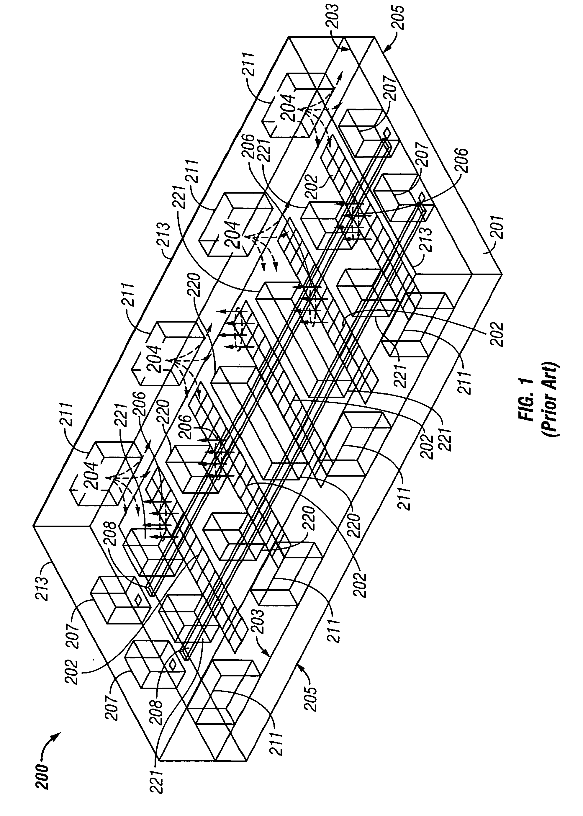
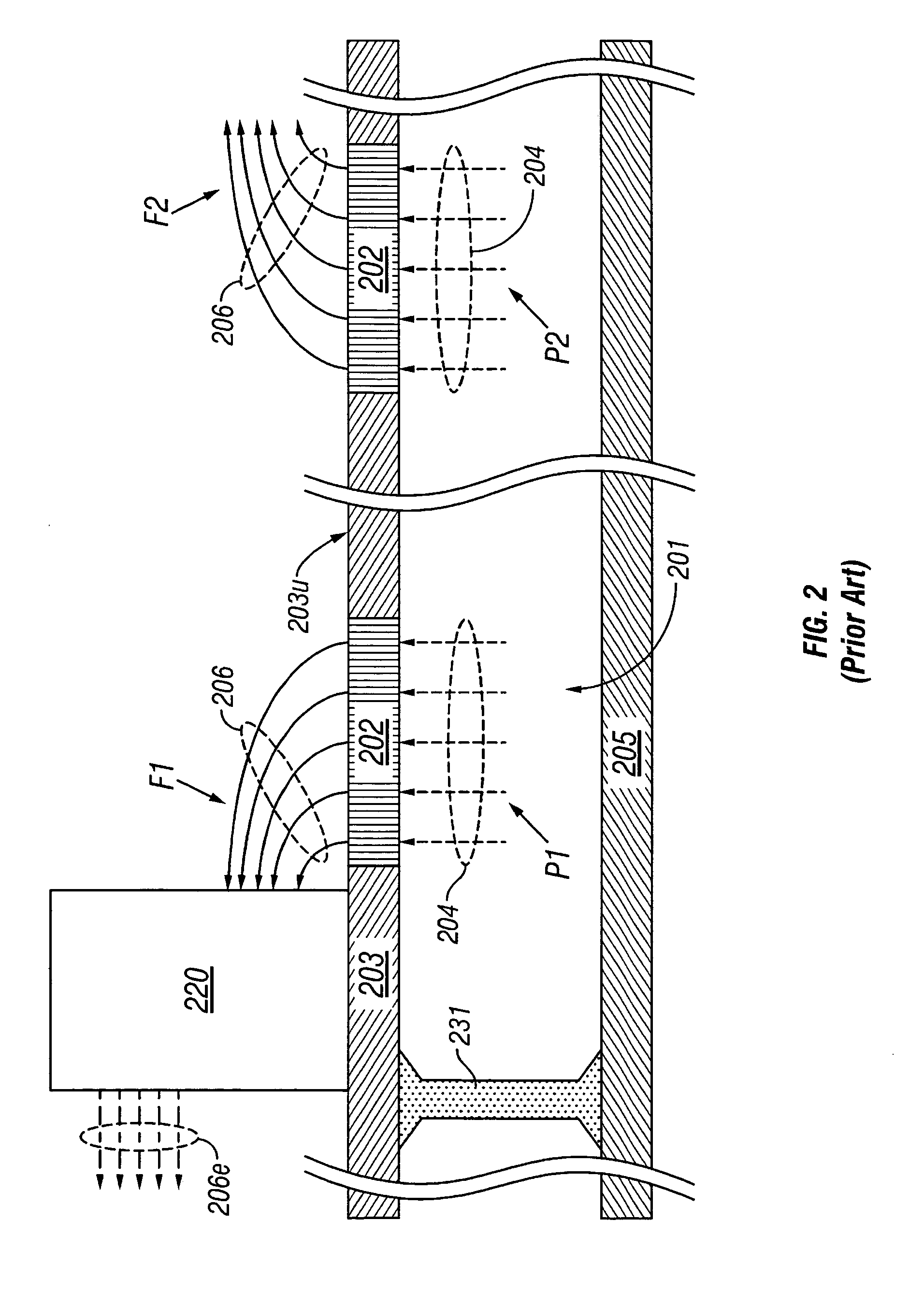
One disadvantage to the UFP 201 is that an air flow rate (e.g. in CFM) of the conditioned air 206 through the vent tiles 202 is mainly influenced by a local static head pressure in the UFP 201.
In either case, the resulting air flow rate may not be sufficient to meet the cooling requirements of some components.
An insufficient air flow rate can be detrimental to components that require a high air flow rate to adequately dissipate waste heat.
If the high density rack is positioned near vent tiles 202 that have an insufficient air flow rate, one or more of the components in the rack can fail due to overheating.
Moreover, it can be costly in terms of labor, rerouting cables, and system down time to move the high density rack to a location on the raised floor 203 where there is a sufficient air flow through the vent tiles 202 to meet the cooling needs of the high density rack.

Method used


Image

  • Intensifier
  • Intensifier
  • Intensifier

Examples


Embodiment Construction

[0038] In the following detailed description and in the several figures of the drawings, like elements are identified with like reference numerals.

[0039] As shown in the drawings for purpose of illustration, the present invention is embodied in an intensifier comprising an enclosure that includes an intake port, an exhaust port, an interior surface that defines a chamber, and an air flow source in communication with the chamber. The enclosure can be positioned in a space that includes an ambient at a first pressure and the exhaust port can be positioned adjacent to an opening in a surface that partially encloses the space. The air flow source draws the ambient into the chamber through the intake port and expels the ambient out of the chamber through the exhaust port at a second pressure that is higher than the first pressure.

[0040] Turning to FIGS. 3a and 3b, an intensifier 10 includes an enclosure 11 that includes an intake port 12, an exhaust port 14, and an interior surface 13 ...


PUM


Abstract

An intensifier is disclosed. The intensifier includes an enclosure with an intake port, an exhaust port, an interior surface that defines a chamber, and an air flow source in communication with the chamber. The intensifier can be positioned in an under floor plenum of a data center. In the plenum, an ambient at a first pressure is draw into the chamber via the intake port and is expelled out of the chamber via the exhaust port and at a second pressure that is higher than the first pressure. The ambient expelled from the intensifier can pass through a vent tile in a raised floor of the data center and the ambient can be used to cool a component supported by the raised floor.

Description

FIELD OF THE INVENTION [0001] The present invention relates generally to an intensifier. More specifically, the present invention relates to an intensifier that generates an air flow at a high flow rate and the air flow can be used to cool a component positioned adjacent to the intensifier. BACKGROUND OF THE INVENTION [0002] A data center is a type of computer room in which one or more components are positioned in the data center and are cooled by conditioned air circulating in the data center. Typical components include computers, PC's, servers, printers, disk arrays, network equipment, backup power supplies, and monitors, just to name a few. The conditioned air can be supplied by one or more computer room air conditioning units (CRAC) that may also be positioned in the data center. [0003] In FIG. 1, a prior data center 200 can include walls 213 and a raised floor 203 that is positioned above a sub-floor 205 with the raised floor 203 supporting components (220, 221). The data cente...

Claims


Application Information

Patent Timeline
Patent Type & Authority Applications(United States)
IPC IPC(8): F24F7/00
CPCF24F11/0001F24F2221/40H05K7/20745
Inventor NAIR, MANU KUMAR VELAYUDHANDANIEL, PREMJITGETTIMALL, GOVINDARAJ
Owner HEWLETT PACKARD DEV CO LP
Learn More