
Compacting device for a machine for winding a fibrous texture onto an impregnation mandrel

Active Publication Date: 2014-04-24
SN DETUDE & DE CONSTR DE MOTEURS DAVIATION S N E C M A
View PDF2 Cites 13 Cited by
  • Summary
  • Abstract
  • Description
  • Claims
  • Application Information

AI Technical Summary

Benefits of technology

The compacting device described in the patent text allows for effective application of tension on a fiber texture while it is being wound onto an impregnation mandrel. This compacting effect enables the preform to achieve its final compacting level and apply a winding tension to fix this level of compacting. The device also includes means for applying vibration to enhance the compacting effect, adjusting the position of the compacting roller and wheels, and using an elastomer coating for better adhesion to the mandrel. The technical effects are improved production efficiency and quality of the finished product.

Problems solved by technology

Practical implementation of that method raises the problem of transferring the fiber texture from the takeup mandrel onto the impregnation mandrel.

Method used


Image

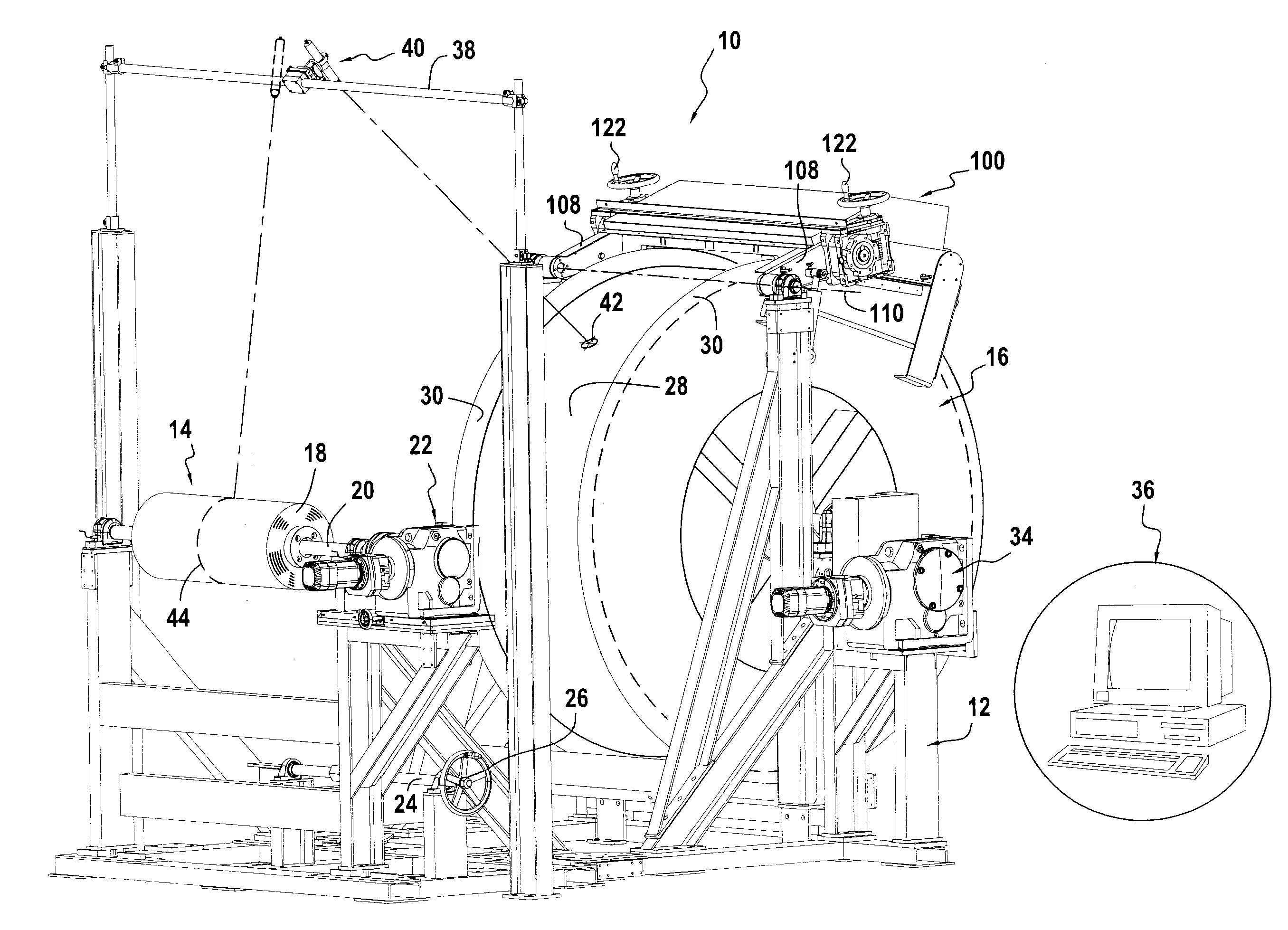
  • Compacting device for a machine for winding a fibrous texture onto an impregnation mandrel
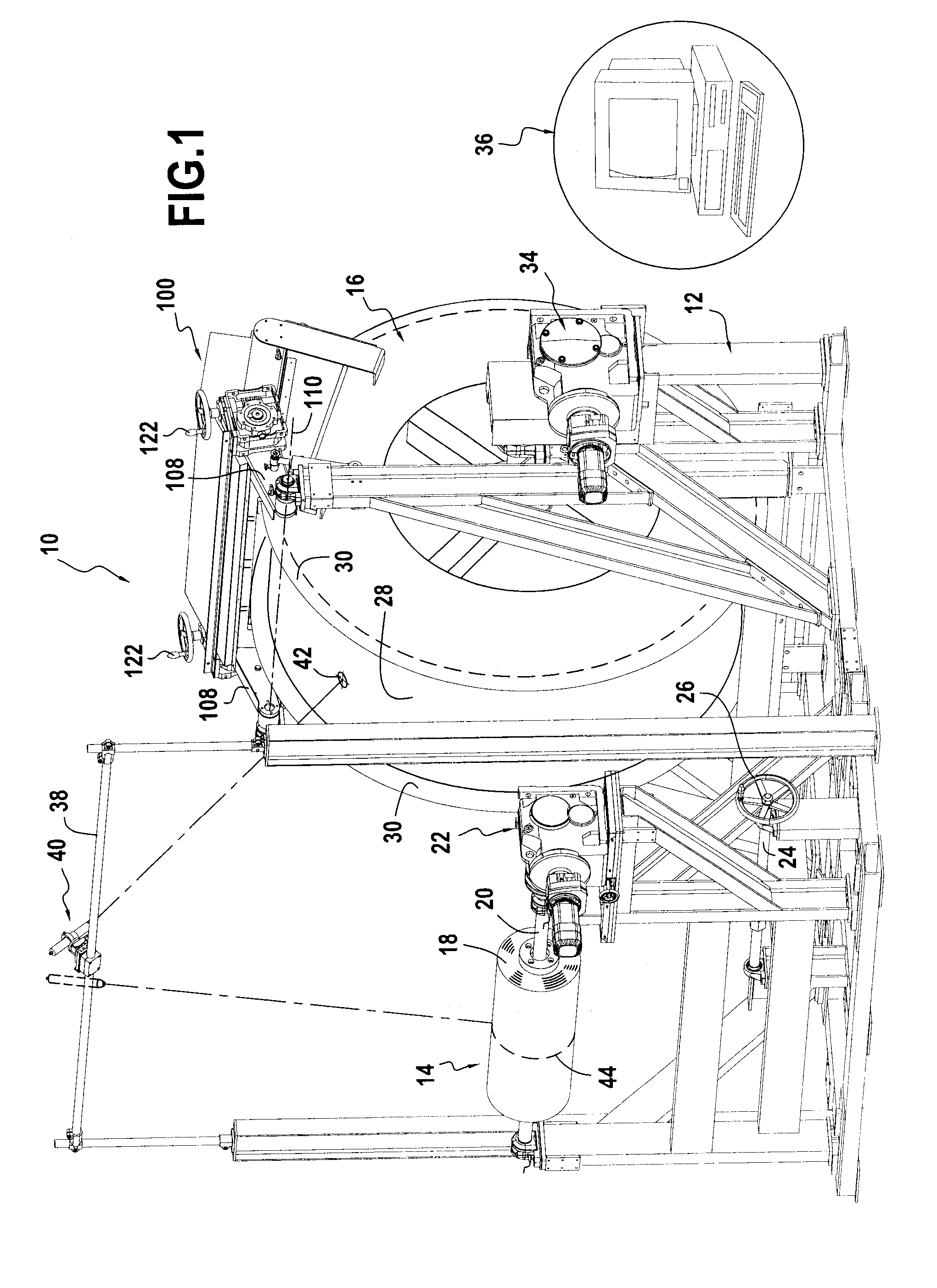
  • Compacting device for a machine for winding a fibrous texture onto an impregnation mandrel
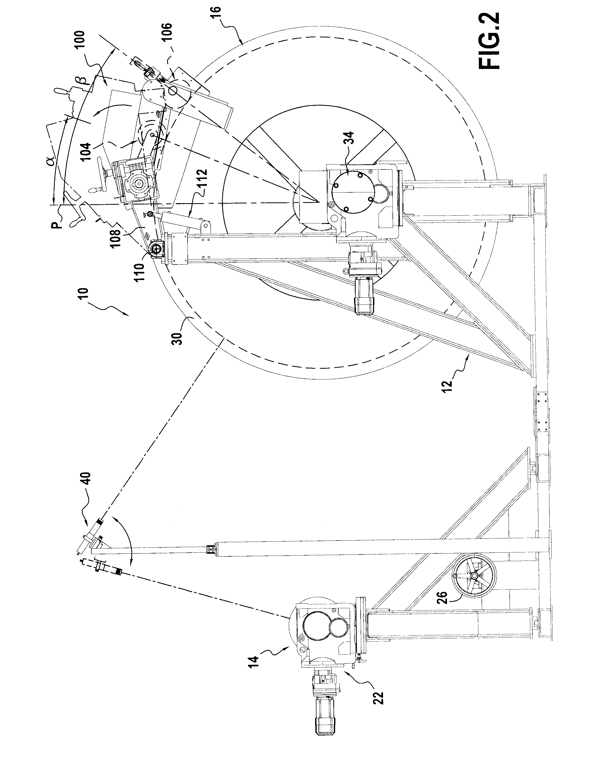
  • Compacting device for a machine for winding a fibrous texture onto an impregnation mandrel

Examples


Embodiment Construction

[0027]The invention is described below in the context of its application to fabricating a fan casing for a gas turbine aeroengine.

[0028]An example of a method of fabricating such a fan casing is described in document EP 1 961 923, to which reference may be made.

[0029]The casing is made of composite material comprising fiber reinforcement densified with a matrix. The reinforcement is made of fibers, e.g. carbon, glass, aramid, or ceramic fibers, and the matrix is made of polymer, e.g. epoxy, bismaleimide, or polyimide.

[0030]Briefly, the fabrication method described in this document consists in making a fiber texture by three-dimensional weaving with warp takeup on a drum (referred to below as a “takeup mandrel”) having a profile that is determined as a function of the profile of the casing to be fabricated. In particular, the fiber texture is made as a single piece with a central portion corresponding to the central portion of the casing that is to be fabricated and with two flanges ...


PUM


Abstract

A compacting device for a machine for winding a fiber texture on an impregnation mandrel, the device including a frame including mounted thereon a compacting roller for bearing against an outside surface of an impregnation mandrel of a winding machine, and two compacting wheels, each configured to bear against a corner formed between the outside surface and a side plate of the impregnation mandrel.

Description

BACKGROUND OF THE INVENTION[0001]The present invention relates to the general field of making gas turbine casings out of composite material, and it relates more particularly to gas turbine fan retention casings for aeroengines.[0002]In a gas turbine aeroengine, a fan casing performs several functions: it defines the air inlet passage into the engine, it supports an abradable material facing the tips of the fan blades, it supports an optional structure for absorbing sound waves for acoustic treatment at the inlet of the engine, and it incorporates or supports a retention shield. The shield constitutes a trap for retaining debris, such as ingested articles or fragments of damaged blades that are thrown outwards by centrifuging, in order to prevent them from passing through the casing and reaching other portions of the aircraft.[0003]A fan retention casing is commonly constituted by a relatively thin wall defining the air inlet passage and supporting an abradable material overlying the...

Claims


Application Information

Patent Timeline
IPC IPC(8): B32B37/00
CPCB32B37/0046B29C53/8083B29C70/32B29C53/562B29C53/566B29C53/8075B29C2053/8025B29L2031/7504
Inventor MATHON, RICHARDPHELIPPEAU, ANTOINEGUMMEL, MICAHDURAND, JEAN-FRANCOIS
Owner SN DETUDE & DE CONSTR DE MOTEURS DAVIATION S N E C M A
Learn More