
System and architecture for merchant integration of a biometric payment system

a biometric payment and merchant technology, applied in payment protocols, instruments, individual entry/exit registers, etc., can solve the problems of increasing the cost of merchant hardware, requiring a substantial amount of hardware, and incurring additional costs for merchants for each client hardware device and associated cables

Inactive Publication Date: 2014-04-17
YOUTECH
View PDF8 Cites 250 Cited by
  • Summary
  • Abstract
  • Description
  • Claims
  • Application Information

AI Technical Summary

Benefits of technology

The patent describes a system and method for authentication and electronic wallet presentation at a merchant location. The system includes a shared central processing server, software components in each POS workstation, and an identity provider service. The shared central processing server receives biometric information from the POS workstations and compares it with registered biometric information to verify the transaction. The method also involves receiving biometric information from multiple checkout areas, determining the checkout area associated with the electronic wallet, and transmitting the representation of the electronic wallet to the checkout area. The technical effects of this innovation include improved security and efficiency for electronic wallet presentation.

Problems solved by technology

One problem with such cross-merchant payment systems is that each checkout area in a merchant environment requires a substantial amount of hardware.
Each client hardware device and associated cables incurs an additional expense from the merchant on a per checkout area basis.

Method used


Image

  • System and architecture for merchant integration of a biometric payment system
  • System and architecture for merchant integration of a biometric payment system
  • System and architecture for merchant integration of a biometric payment system

Examples


Embodiment Construction

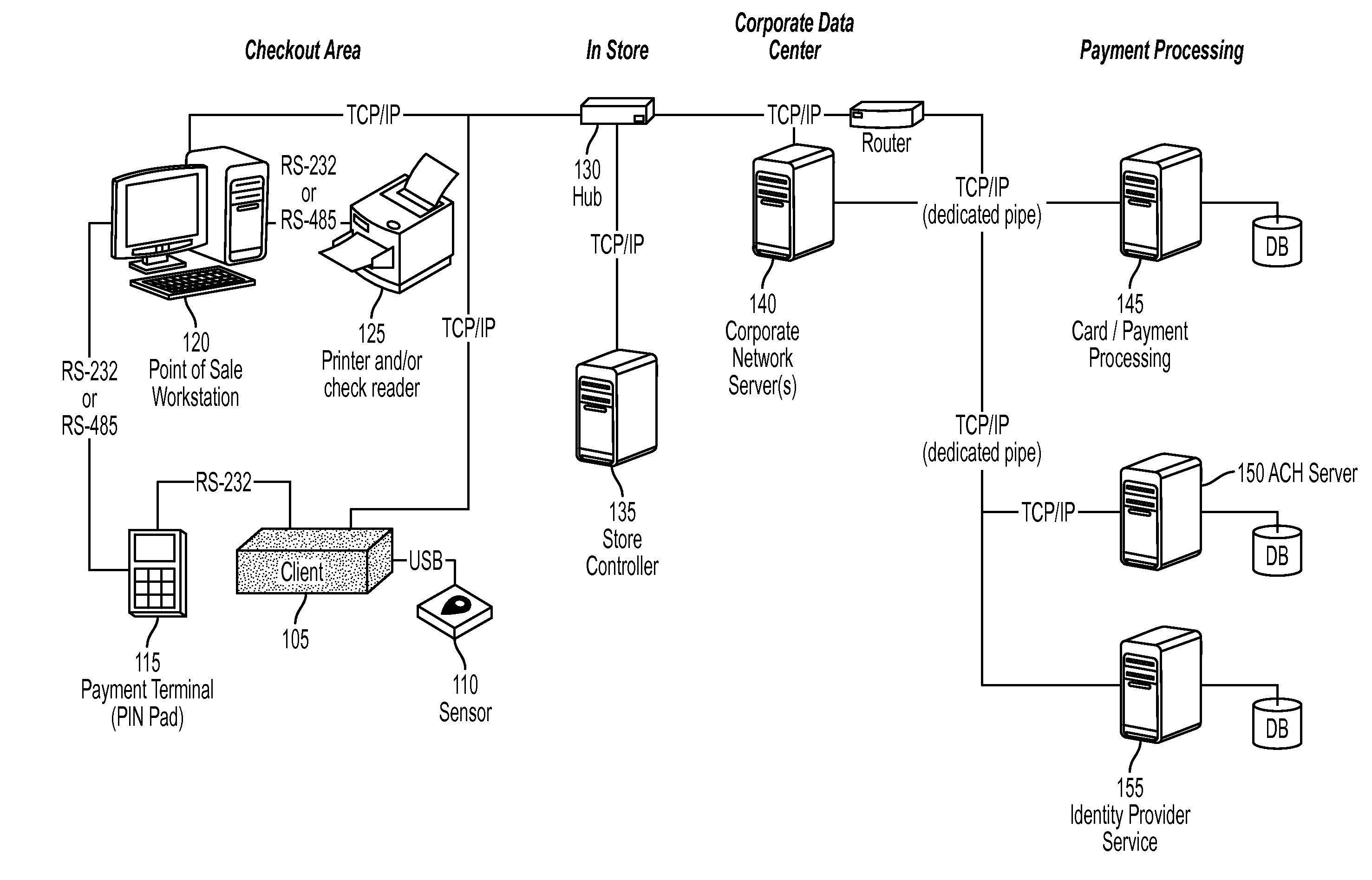
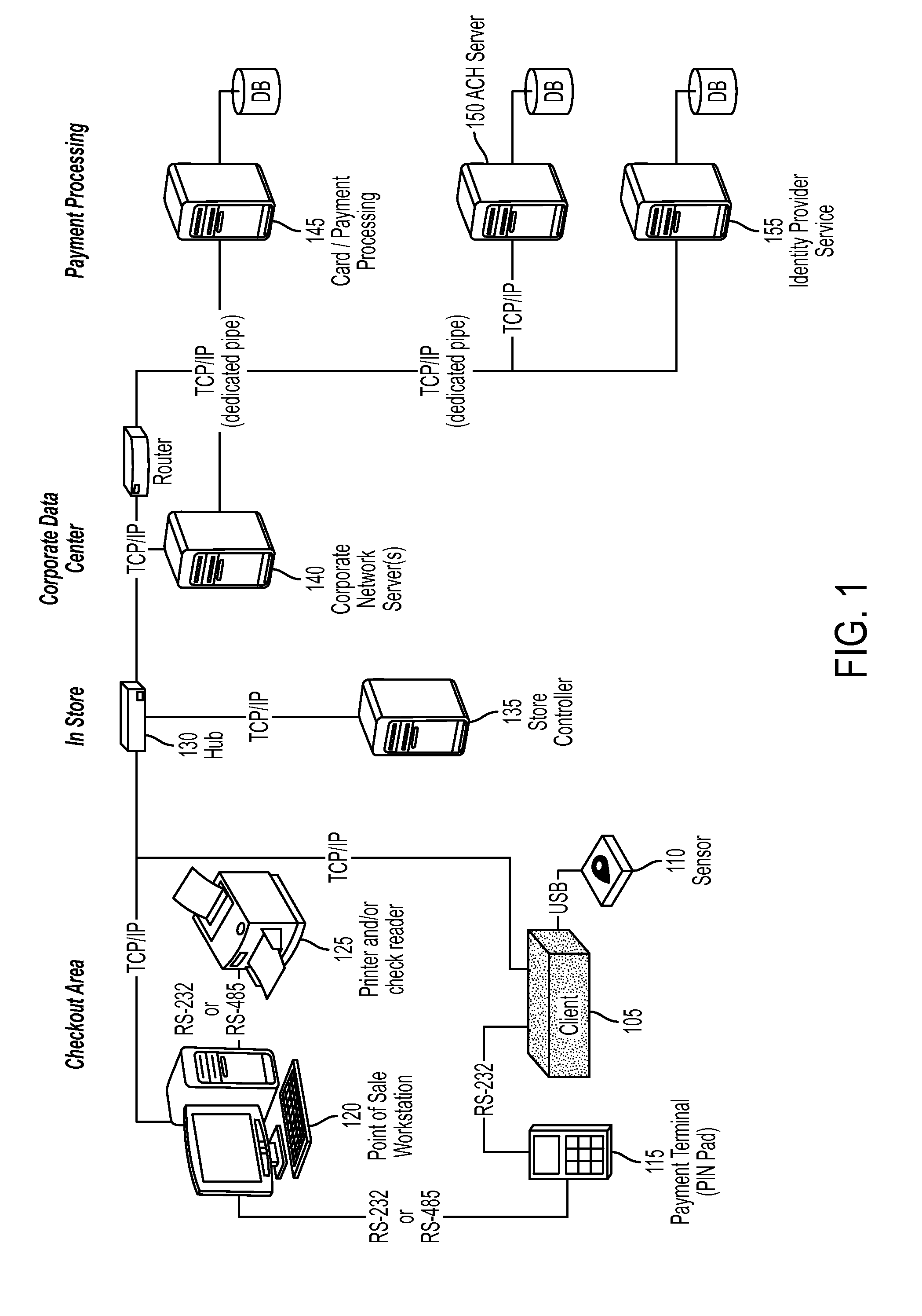
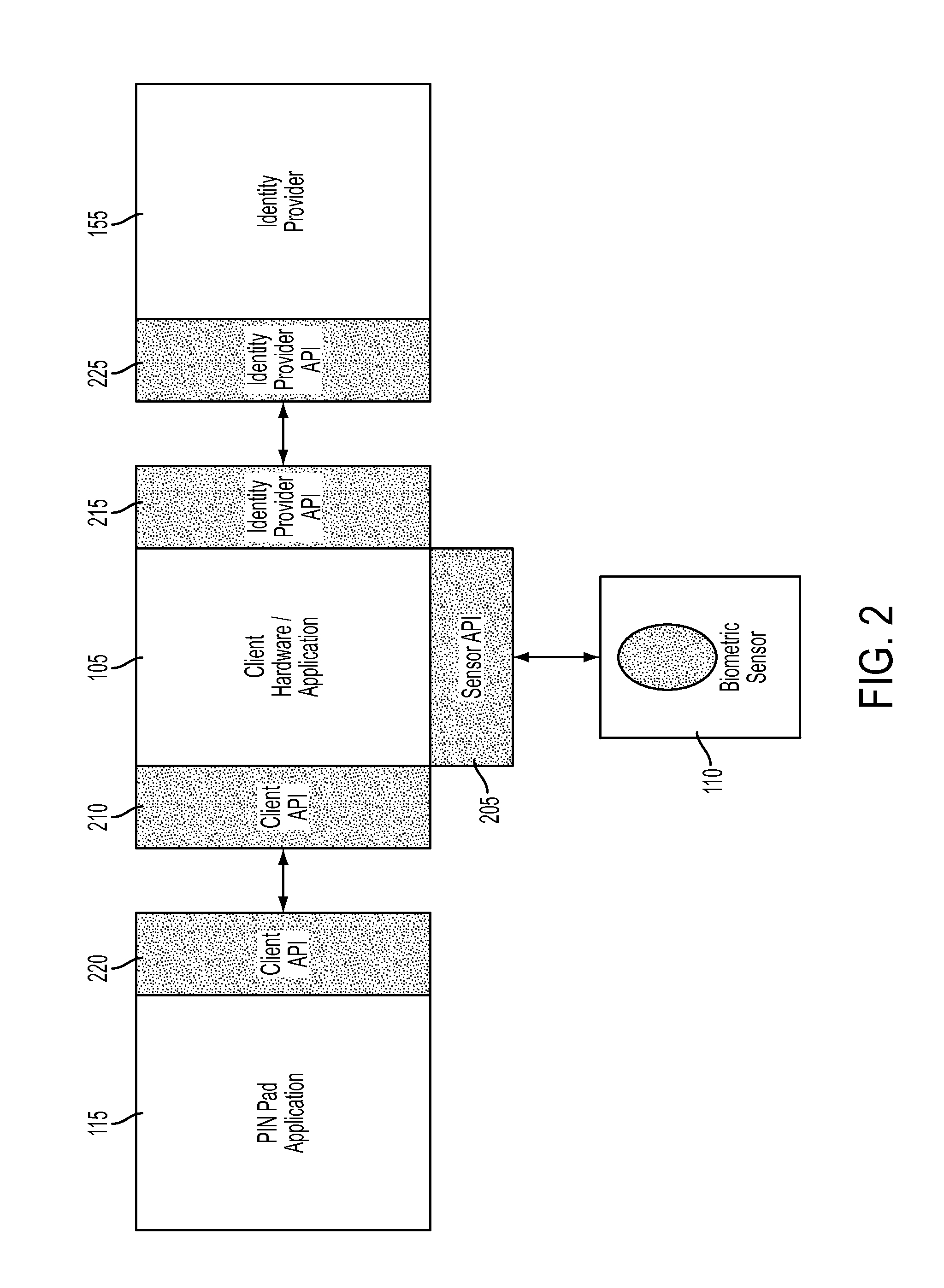
[0025]In an embodiment, the amount of additional hardware required for a checkout area may be substantially reduced. For example, in a checkout lane for the implementation of biometrically enhanced cross-merchant payment system, only a biometric sensor, such as a fingerprint sensor, a retinal scanner, a voice recorder or the like, may need to be added to a conventional non-biometric, non-cross-merchant checkout environment. The biometric sensor may be in communication with the POS workstation via, for example, a Universal Serial Bus (“USB”) port. The POS workstation and / or PIN pad may include additional software components to control operation of the biometric sensor and to communicate with the identity service provider. In an embodiment, the biometric sensor may merely require a connection to the POS workstation, and not LAN and / or power connections.

[0026]FIG. 3 depicts a block diagram for an exemplary cross-merchant payment and authentication system according to an embodiment. As ...


PUM


Abstract

A system and method for performing authentication are disclosed. The system may include a shared central processing server, a plurality of software components each residing in a corresponding point-of-sale (POS) workstation and an identity provider service. The server may reside at a merchant location and communicate with multiple POS workstations at the merchant location. The server may be configured to receive biometric information from each POS workstation. Each software component may communicate with a biometric sensor in communication with the corresponding POS workstation to receive biometric information. The identity provider service may be configured to communicate with the server, store registered biometric information and compare biometric information received from the server with one or more of the stored registered biometric information. One of the biometric sensor, a POS workstation and the server may convert a biometric image into a biometric template for comparison with the stored registered biometric information.

Description

CROSS-REFERENCE TO RELATED APPLICATIONS[0001]This application is a continuation of U.S. application Ser. No. 11 / 421,451, filed May 31, 2006, entitled SYSTEM AND ARCHITECTURE FOR MERCHANT INTEGRATION OF A BIOMETRIC PAYMENT SYSTEM, now issued U.S. Pat. No. 8,589,238, issued on Nov. 19, 2013, herein incorporated by reference.BACKGROUND OF THE INVENTION[0002]Conventional merchant payment systems typically include one or more point-of-sale workstations (“POS workstations”), such as an electronic cash register (“ECR”) that may be coupled to a payment terminal, such as a PIN pad card reader (“PIN pad”) to accommodate credit and debit card payments from consumers. The ECR is coupled through a network connection (e.g., broadband connection or dial-up connection) at the merchant location in order to interact with remote card payment processing systems to process credit card and debit card transactions initiated by consumers for settlement. A merchant may have multiple checkout lanes each with...

Claims


Application Information

Patent Timeline
IPC IPC(8): G06Q20/20
CPCG06Q20/206G06Q10/067G06Q20/12G06Q20/20G06Q20/40G06Q20/4014G07C9/37
Inventor COOPER, BRIANHILMES, RON
Owner YOUTECH
Learn More