
Method for calibrating and correcting the scanning distortion of an optical coherence tomography system

a technology of optical coherence tomography and scanning distortion, applied in the field of calibrating and correcting the scanning distortion of an optical coherence tomography system, can solve the problems of limited use of the optical coherence tomography (oct) technique as a topographical technique, field distortion and astigmatism in images, and flat mirrors, etc., to achieve the effect of improving the optical coherence tomography techniqu

Active Publication Date: 2014-04-17
CONSEJO SUPERIOR DE INVESTIGACIONES CIENTIFICAS (CSIC)
View PDF2 Cites 12 Cited by
  • Summary
  • Abstract
  • Description
  • Claims
  • Application Information

AI Technical Summary

Benefits of technology

The present invention is an improvement on optical coherence tomography, which allows for the accurate and precise imaging of surfaces. It can be used with any optical coherence tomography system and provides quantitative data on the topography of surfaces, particularly ocular surfaces. This technique is advantageous over other existing methods.

Problems solved by technology

In general, the use of the optical coherence tomography (OCT) technique as a topographical technique is limited by the presence of scanning distortion associated with the architecture of the sweep system (generally formed by a 2-axle mirror scanner), which also produces field distortion and astigmatism in the images.
The main factor contributing to this distortion is the separation of the mirrors in the scanner and the focal length of the lens that collimates the beam on the sample and, to a lesser extent, the flatness of the mirrors and misalignment of the rotation beam of the mirrors.
However, in systems with two scanners, with three dimensional acquisition of data, distortion is complex since it is not linear and has dependencies between the lateral and axial positions, as well as being dependent on the optical and geometrical configuration of each piece of equipment.
This complexity has generally prevented quantitative three-dimensional topographical data from being obtained.
Nevertheless, the correction of the scanning distortion in these commercial systems has not been proven, as is the case in one of the most widespread previous commercial systems (Visante, Zeiss) based on Placido rings, despite it providing three-dimensional corneal elevation data.
However, this does not produce the claimed distortion correction but rather it produces the opposite effect, as the beams have to transverse very different paths.
However, this method requires the use of a confocal channel to obtain the scanning distortion.
This confocal channel is not generally available in Optical Coherence Tomography instruments, which is why the method is not generally applicable.
Patents U.S. Pat. No. 716,313 and U.S. Pat. No. 5,491,524 describe corneal topographic mapping systems by means of optical coherence tomography but they do not disclose the correction of the scanning distortion.

Method used


Image

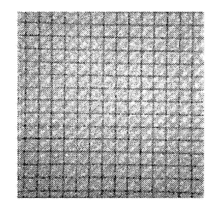
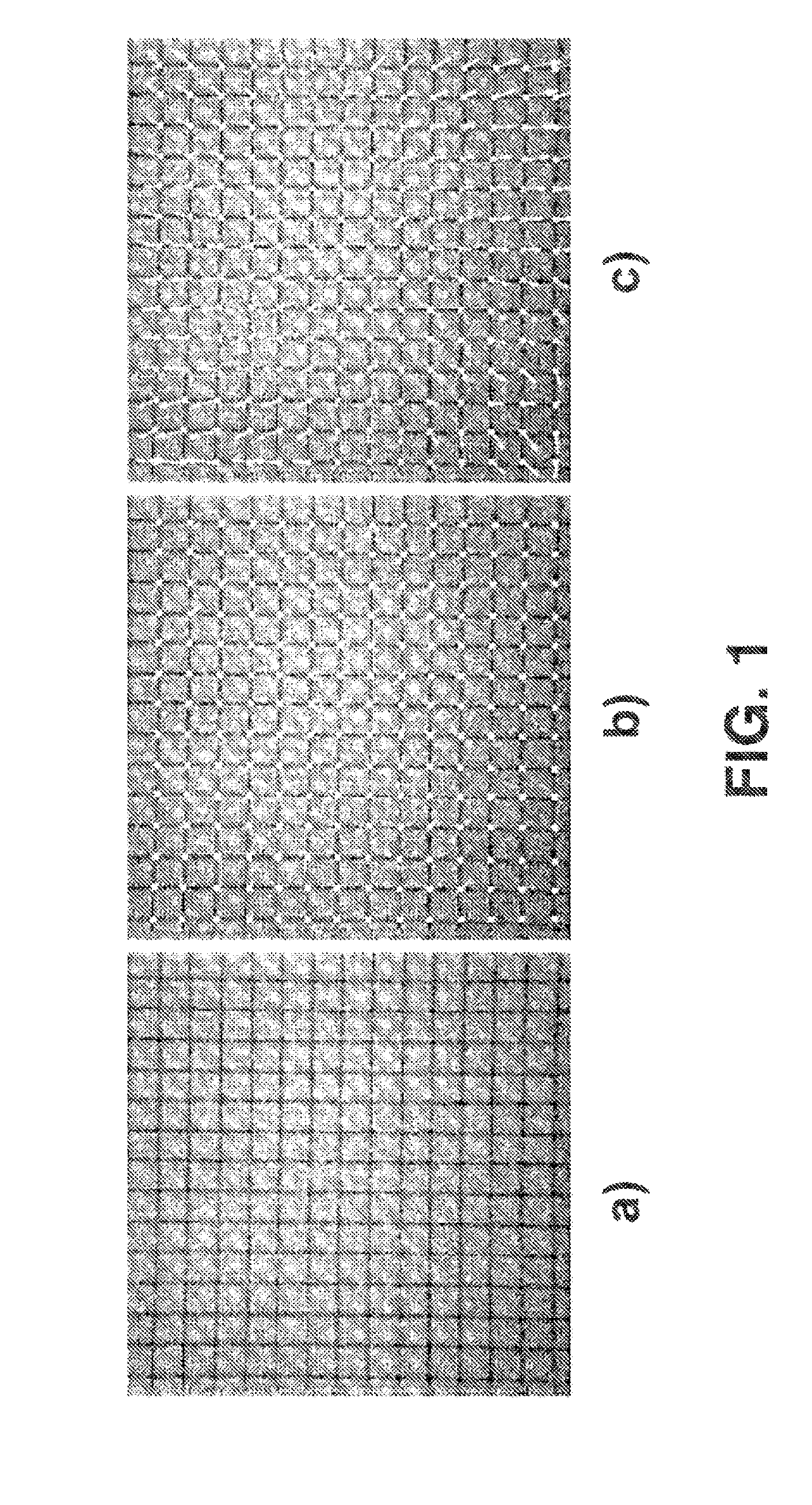
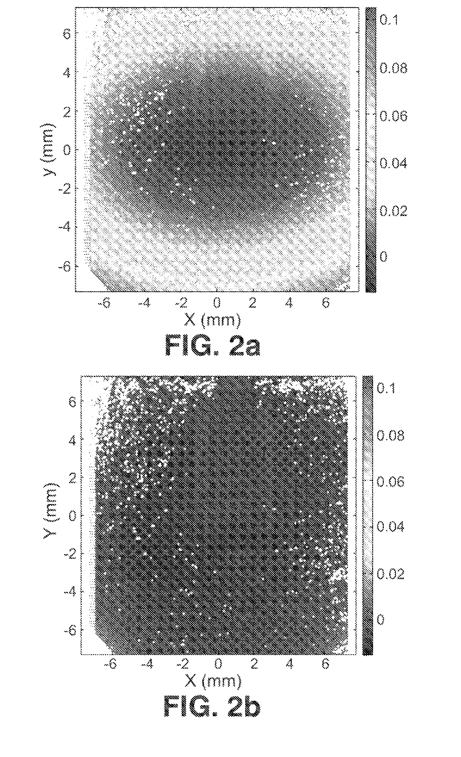
  • Method for calibrating and correcting the scanning distortion of an optical coherence tomography system
  • Method for calibrating and correcting the scanning distortion of an optical coherence tomography system
  • Method for calibrating and correcting the scanning distortion of an optical coherence tomography system

Examples


Embodiment Construction

[0017]In order to fulfill the objectives and avoid the limitations set out above, the invention consists of a method for calibrating any kind of optical coherence tomography system.

[0018]The method of the present invention is proposed as a calibration protocol for any optical coherence tomography system for obtaining quantitative topographical maps based on three-dimensional optical coherence tomography images of the sample. The method allows correcting distortion in any optical coherence tomography system, independently of its specific optical and geometric configuration, in comparison to other methods described, which are limited to one particular configuration of the system or to two-dimensional images or they adopt a hypothesis that requires previous knowledge of the system, including the arrangement of the elements thereof and the system alignment and response. The present invention approaches the empirical measurement of system scanning distortion, determining, via use of a re...


PUM


Abstract

Method for calibrating and correcting the scanning distortion of any optical coherence tomography system by using reference patterns and obtaining mathematical relationships between the positions of the reference points in a reference pattern and the local coordinates of said reference points, said coordinates are obtained by means of said optical coherence tomography system.

Description

OBJECT OF THE INVENTION[0001]The present invention, as formulated in this descriptive specification, refers to a method for calibrating and correcting the scanning distortion of optical coherence tomography systems.[0002]The present invention improves the optical coherence tomography technique, since the method described in the invention allows obtaining a two-dimensional and three-dimensional quantitative tomography of surfaces based on optical coherence tomography images. The method may be applied to any optical coherence tomography system wherein the scanning system of the tomography system is based on a 2-axis scanning system.[0003]The present invention constitutes an improvement on the state of the art, since it allows quantifying images obtained using optical coherence tomography techniques and to obtain topographical maps of general surfaces and more specifically, of ocular surfaces, thereby being more advantageous than alternative existing techniques.[0004]The present invent...

Claims


Application Information

Patent Timeline
IPC IPC(8): G01B9/02
CPCG01B9/02076G01B9/0209A61B3/102A61B5/0066A61B2560/0233G06T2207/10101G01B9/02072G01B9/02091G01B2290/65G06T7/80G06T5/80A61B6/02
Inventor ORITZ EGEA, SERGIOMARCOS CELESTINO, SUSANASIEDLECKI, DAMIANDORRONSORO DIAZ, CARLOS
Owner CONSEJO SUPERIOR DE INVESTIGACIONES CIENTIFICAS (CSIC)
Learn More