
Apparatus for monitoring intra-abdominal pressure

a technology for intra-abdominal pressure and abdominal cavity, applied in the field of abdominal cavity monitoring apparatus, can solve the problems of organ damage and patient death, tissue edema in the body, increased risk of infection for both patient and health practitioner, etc., and achieve the effect of improving speed

Inactive Publication Date: 2014-03-27
CONVATEC TECH INC
View PDF25 Cites 84 Cited by
  • Summary
  • Abstract
  • Description
  • Claims
  • Application Information

AI Technical Summary

Benefits of technology

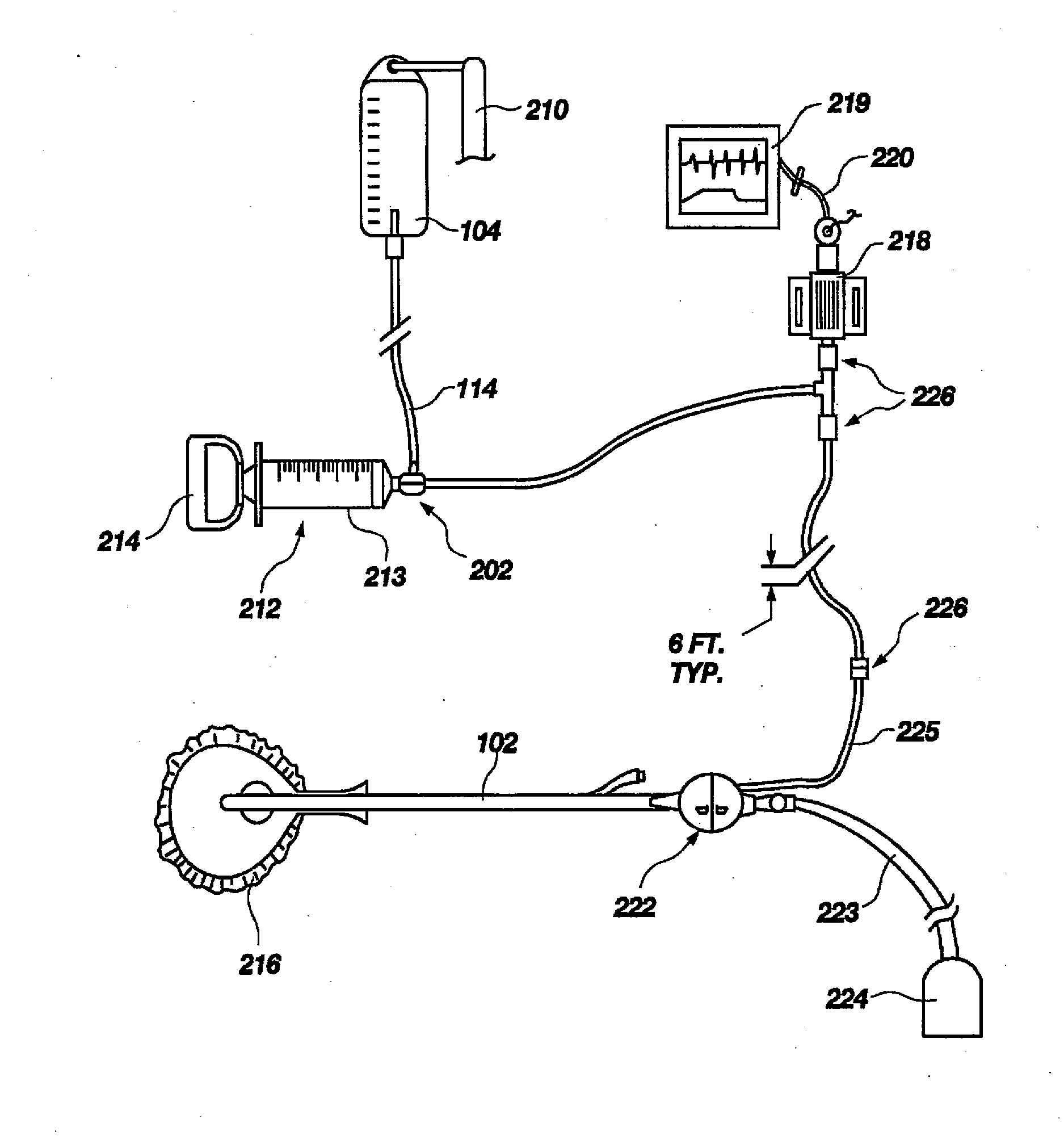
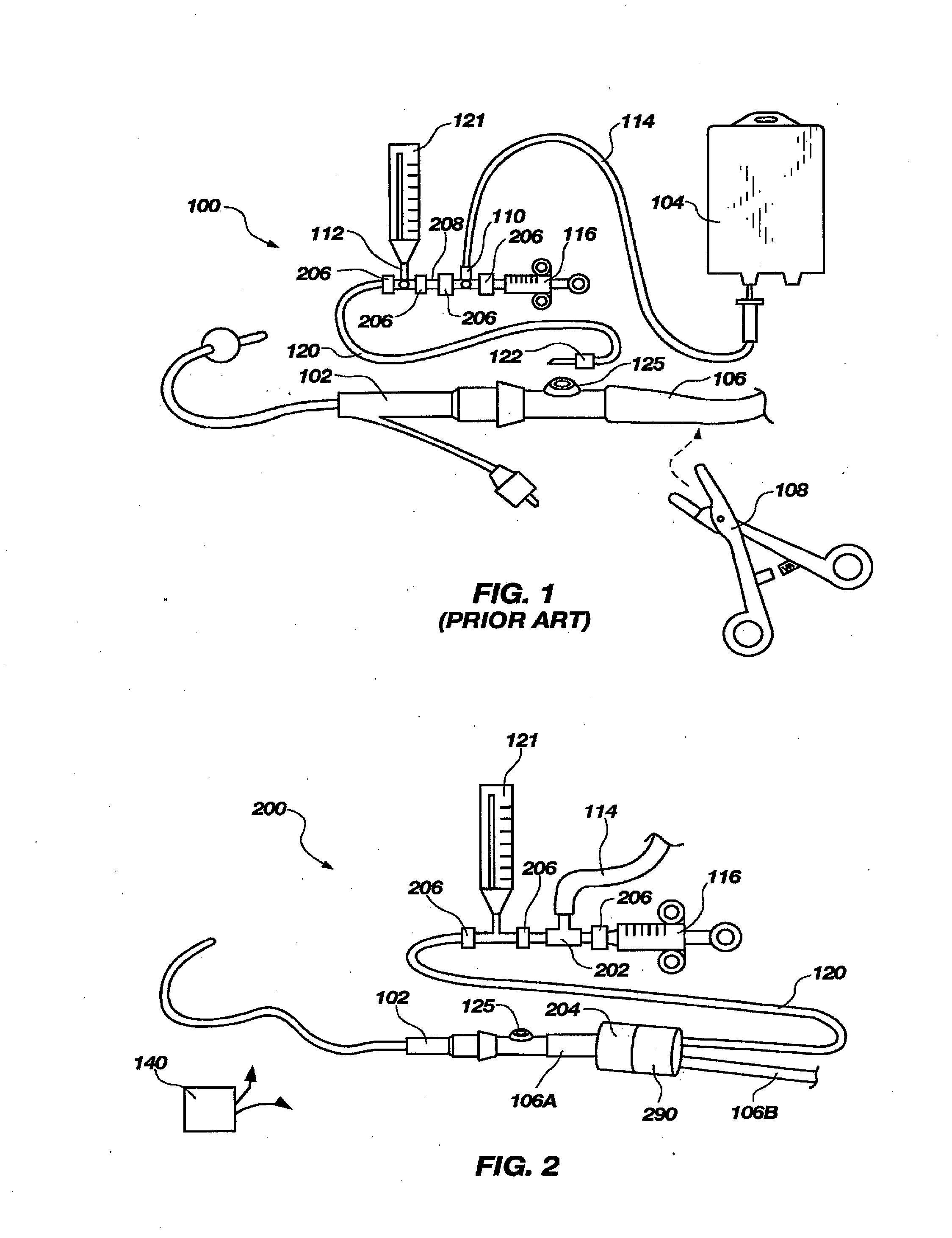
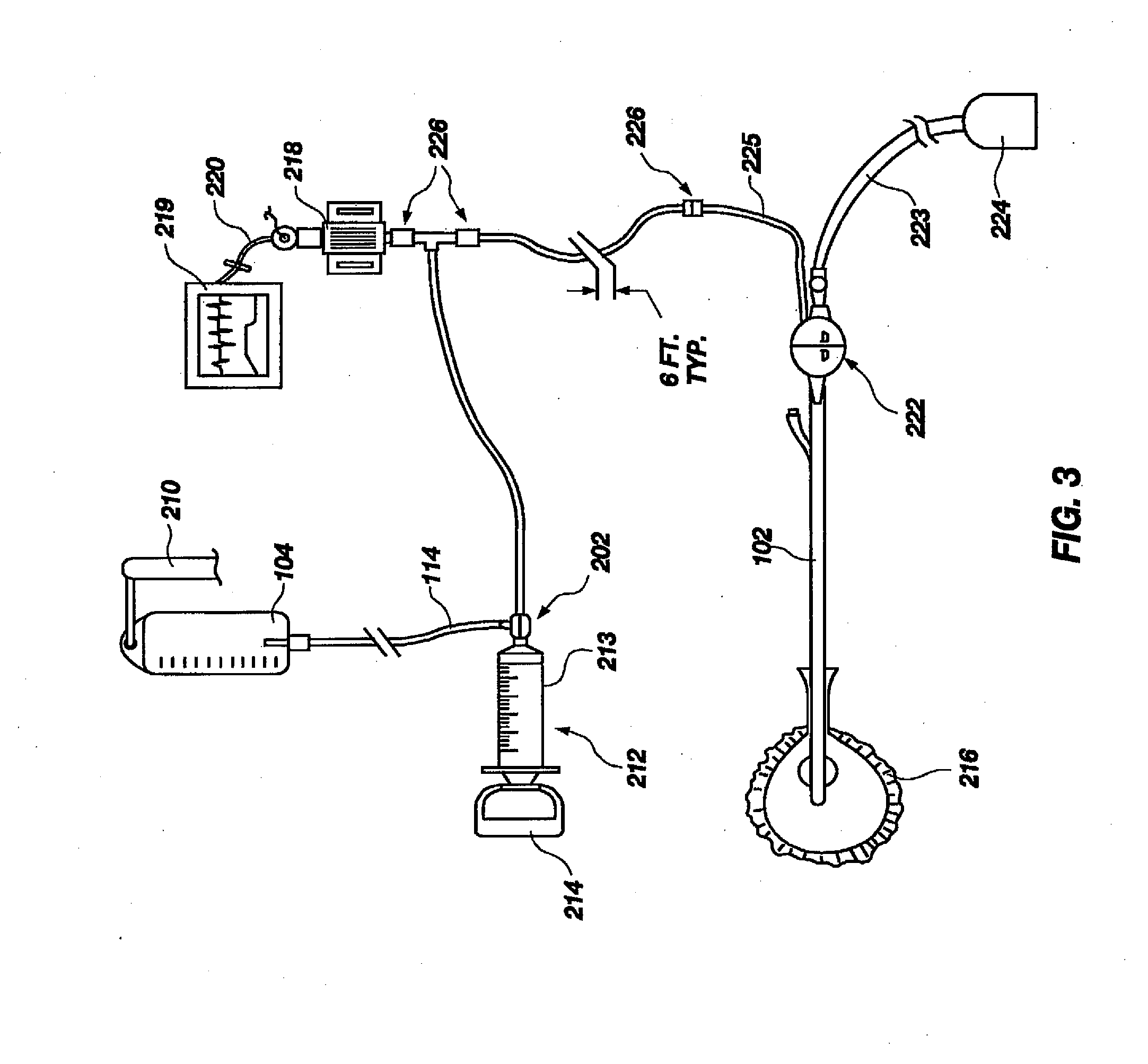
The patent describes an apparatus and method for measuring hydraulic pressure in a patient's bladder to infer intra-abdominal pressure. The apparatus includes a catheter, a container of fluid, a fluid pump, a pressure transducer, and an automatic flow-control device. The flow-control device permits fluid flow from the container towards the patient's bladder and resists fluid flow back towards the pump. The apparatus also includes a urine valve to facilitate making a pressure measurement and a protective housing to prevent injury to the patient. The technical effects of the patent are improved accuracy and speed in measuring intra-abdominal pressure and increased safety during the procedure.

Problems solved by technology

Elevated intra-abdominal pressure leads to major changes in the body's physiology that, if undetected and untreated, can result in organ damage and patient death.
When patients become critically ill, they may develop a capillary leak phenomenon that causes the tissues in their body to become edematous with extra fluid that seeps out of the capillaries.
Unfortunately, opening the closed drainage system plumbing places both the patient and the health practitioner at increased risk of infection.
It is possible to use a three-way Foley catheter, but such catheters are more expensive and are not routinely used.
The former option increases costs, and the latter would increase both costs and risk of patient infection.
Undesirably, approaches involving use of needles, particularly in the vicinity of the patient's legs to assemble the pressure measuring apparatus, place both the patient and the health practitioner at risk of needle sticks.
However, operable medical grade valves that are commercially available, such as two-way or three-way stopcocks 110 and 112, typically introduce undesired complications.
One complication is that the available medical grade stopcocks typically provide drainage passageways that are too small in diameter for use in a urinary catheter drain.
Clogging of the urine drain bore would be a serious problem.
Another complication substantially precluding direct inclusion of available medical grade two-way or three-way valves or stopcocks is that such devices route fluid conduits in orthogonal directions at the valve connection locations, thereby creating protruding and invasive plumbing that is uncomfortable to the patient.
Furthermore, currently available valves and stopcocks also have protrusions (such as valve actuators or handles), and sharp corners or abrupt changes in shape, that place a patient at risk of injury should such protrusion or corner be impressed into a patient's skin.
The procedures for measuring trends in a patient's IAP described above undesirably place a patient at risk of infection, or require tiresome manual adjusting of a plurality of plumbing devices, such as two-way valves or stopcocks.

Method used


Image

  • Apparatus for monitoring intra-abdominal pressure
  • Apparatus for monitoring intra-abdominal pressure
  • Apparatus for monitoring intra-abdominal pressure

Examples


second embodiment

[0092]FIGS. 12 through 15 illustrate a valve, generally indicated at 330, that is configured to provide a streamlined plumbing arrangement to enhance routing of conduits between a patient's legs. Valves 300 and 330 are both of the type that may be characterized as transversely actuated gate valves, with a principal difference being the arrangement of gripping structure to actuate the valve gate 304. Valve 330 has gripping structure 332 arranged to provide a transversely oriented shelf 333. FIGS. 12 through 15 illustrate valve 330 oriented with gate 304 located at an outboard position to align urine port 310 for fluid communication with fluid supply port 320.

[0093]FIG. 13 illustrates one arrangement operable to resist fluid leaks from the fluid flow paths through the valve 330. Grooves 334 and 336 receive O-rings that are adapted to bear against surface 338 of gate 304 (see FIG. 15). It is alternatively within contemplation to form a raised lip about respective openings of lumens thr...

third embodiment

[0097]FIGS. 16 through 19 illustrate a valve, generally indicated at 350, that is configured to provide a streamlined plumbing arrangement to enhance routing of conduits between a patient's legs. Valve 350 is of the type that may be characterized as a rotary actuated gate valve. Valve 350 includes a valve body 352, a rotary gate 354, and a valve cover 356. Body 352 carries grooves 358 and 360 that may hold O-rings, or may provide clearance to promote sealing of lips 362 and 364 against gate surface 366.

[0098]A change in selected flow paths through the illustrated valve 350 is effected by an approximately 90 degree rotation of gate 354 relative to valve body 352. A lever 368 is trapped within arcuate slot 370 during assembly of the valve 350, and is operable to rotate gate 354 to a desired position to permit fluid communication between urine conduit 372 and either of fluid supply port 374 or urine drain 376. Assembly of valve 350 typically is accomplished by ultrasonic welding cover ...


PUM


Abstract

An improved apparatus for monitoring the intra-abdominal pressure of a hospitalized patient includes a urinary catheter connected to a urine valve having selectable communication positions between a discharge end of the urinary catheter and either a drain or a fluid source. Preferably, the urine valve has a housing adapted to resist patient discomfort from leg-valve contact. One operable protective housing may be embodied as a separate tray component. Plumbing structure desirably maintains fluid supply and drain conduits in a substantially parallel arrangement to assist routing those conduits between a patient's legs. When the urine valve is oriented for communication to the fluid source, an infusion pump may be used to introduce a known quantity of fluid through the urine valve and into the patient's bladder where the fluid's pressure can be measured. Desirably, a double check valve is included in a fluid supply path and arranged to permit repetitive operation of a syringe to inject a bolus of fluid into the patient's bladder. Subsequent to making a pressure measurement, the urine valve is returned to the bladder draining position.

Description

CROSS-REFERENCE TO RELATED APPLICATIONS[0001]This application is a continuation of U.S. patent application Ser. No. 11 / 219,319, filed Sep. 1, 2005, U.S. Pat. No. ______, which is a continuation of PCT International Patent Application No. PCT / US2004 / 006409, filed on Mar. 1, 2004, designating the United States of America, and published, in English, as PCT International Publication No. WO 2004 / 078235 A2 on Sep. 16, 2004, which application is a continuation in part of U.S. patent application Ser. No. 10 / 379,222, filed Mar. 4, 2003, for “APPARATUS FOR MONITORING INTRA-ABDOMINAL PRESSURE,” now U.S. Pat. No. 7,112,177 B2 issued Sep. 26, 2006, the entire contents of all of which are incorporated by this reference.TECHNICAL FIELD[0002]The invention relates generally to plumbing devices including valves and conduits, and to pressure measurement equipment. The invention relates particularly to apparatus configured as an assembly to infer intra-abdominal pressure of a medical patient by measuri...

Claims


Application Information

Patent Timeline
Patent Type & Authority Applications(United States)
IPC IPC(8): A61B5/20F16K17/00
CPCF16K17/00A61B5/205A61B5/412Y10T137/7837
Inventor CHRISTENSEN, MARK A.WOLFE, TIMOTHY R.CROLL, PERRY W.DENTON, MARSHALL T.KIMBALL, EDWARD J.
Owner CONVATEC TECH INC
Learn More