LED drive apparatus, systems and methods

a technology of led drive and apparatus, applied in emergency power supply arrangements, instruments, transportation and packaging, etc., can solve problems such as challenging requirements for led application designs, led illuminated micro-display console systems and head-up display systems, and achieve the effect of low dimming ratio and higher dimming ratio

Active Publication Date: 2014-03-27
TEXAS INSTR INC
View PDF10 Cites 24 Cited by
  • Summary
  • Abstract
  • Description
  • Claims
  • Application Information

AI Technical Summary

Benefits of technology

[0023]Apparatus, systems and methods disclosed herein implement dynamic dimming of a color LED array such as may be used in various applications operating in high dynamic range ambient light conditions. Such applications may include projection systems of various types including HUD systems, color display panels, outdoor signage, etc.
[0024]Embodiments herein may operate in one or both of two modes, “continuous mode” (CM) and “discontinuous mode” (DM). Lower dimming ratios are available in CM and higher dimming ratios are available in DM. Consequently, a device or system operating in an extremely wide dynamic range of ambient light may transition back and forth between CM operation during periods of high ambient light and DM operation during periods of low ambient light. Methods and structures herein do not so require, however, as each mode of operation is distinctly supported.
[0025]Both modes of operation use light flux levels sensed from the color LED array as a feedback signal. The light flux feedback signal is used to control both current availability to the LED array and the state of a current bypass switch. The current by...

Problems solved by technology

Automotive LED application designs, such as LED illuminated micro-display ...

Method used


Image

  • LED drive apparatus, systems and methods
  • LED drive apparatus, systems and methods
  • LED drive apparatus, systems and methods

Examples


Embodiment Construction

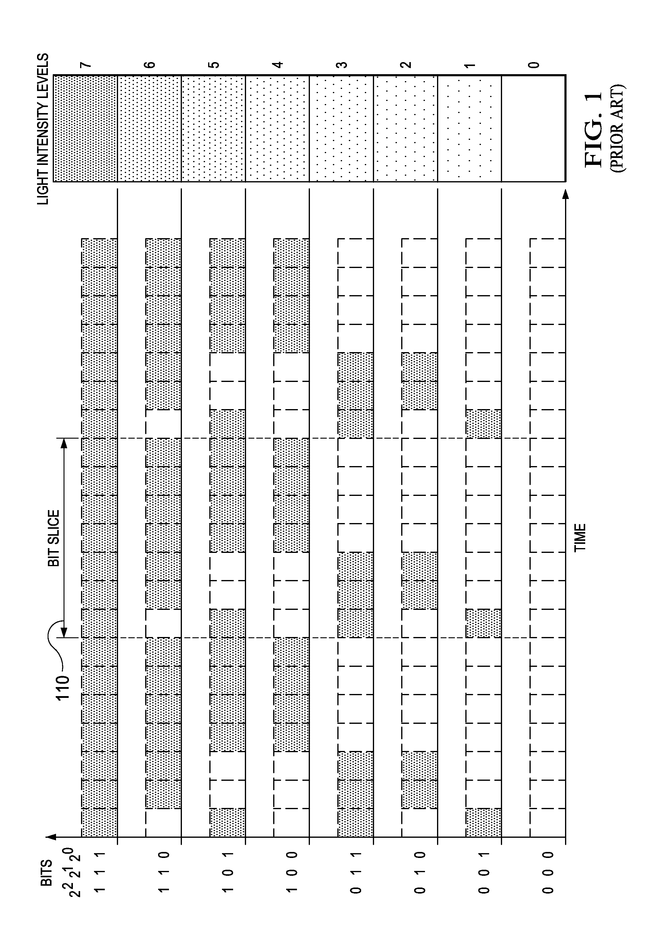
[0029]FIG. 1 is a prior-art diagram illustrating luminance control of a single LED using a three-bit binary word to “bit-weight” a stream of LED drive current pulses. That is, the size of the binary control word determines the average number of current pulses per time applied to the LED. And, the resulting intensity of light emanating from the LED is a function of the average number of current pulses per time. The term “bit-slice” as used herein shall mean a period of time (e.g., the period of time 110) during which one or more pulses of current are applied to an LED.

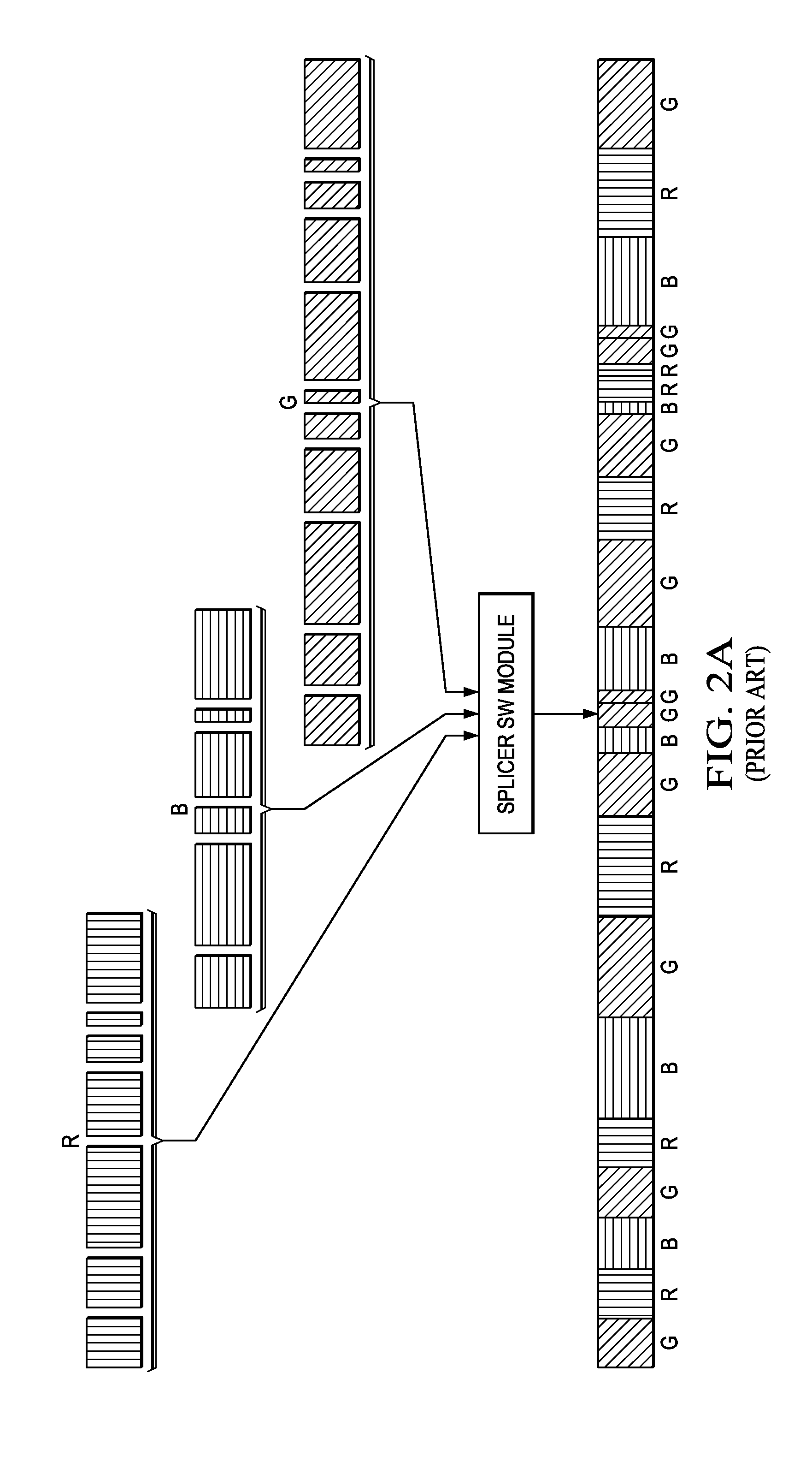
[0030]FIG. 2A is a prior-art diagram illustrating a stream of LED drive current pulses created by combining multiple, differently bit-weighted sub-streams of LED drive current pulses, each sub-stream corresponding to a particular primary color.

[0031]FIG. 2B is a prior-art diagram illustrating various lengths or “bit slices” of LED drive current pulses combined to create an example composite drive current signal 212 to d...


PUM


Abstract

Light flux levels sensed from a color LED array control both current availability to the array and disable/re-enable a current bypass switch to shunt stored-energy current to or away from a selected LED. In continuous mode, a single flux pulse is created for the duration of a pre-established period. Feedback from the flux sensor pulses current to an energy storage device to maintain the light flux at a predetermined set-point. A particular dimming level is achieved by establishing both the pulse period and the flux magnitude. In discontinuous mode, one or more short flux pulses are created. Both the turn-on and the turn-off time of each flux pulse is controlled by alternately removing and then re-establishing a current shunt from the energy storage device to ground. Flux pulse magnitude is controlled by recognizing when the flux pulse has reached a predetermined set-point and re-establishing the current shunt to abruptly turn off current to the selected LED.

Description

PRIORITY CLAIM[0001]This application claims the benefit of priority under 35 U.S.C. §119(e) to U.S. Provisional Patent Application Ser. No. 61 / 704,131 titled “LED Drive Method and Apparatus,” filed on Sep. 21, 2012 and incorporated herein by reference in its entirety.TECHNICAL FIELD[0002]Structures and methods described herein relate to light-emitting diodes (LEDs), including LED luminance control suitable for high dynamic range ambient light environments.BACKGROUND INFORMATION[0003]Automotive LED application designs, such as LED illuminated micro-display console systems and Head-up Display (HUD) systems, face challenging requirements. These include extended operating temperature range, very wide dimming ratio (ratio of fullest brightness image for full sunlight to lowest brightness image for night darkness), and very tight / high quality color point control requirements.[0004]Typical solutions use LED current as the primary feedback mechanism. Some solutions perform dimming by decrea...

Claims


Application Information

Patent Timeline
IPC IPC(8): H05B33/08G02B27/01H05B44/00
CPCG02B27/01H05B33/0827H05B45/20H05B45/3725H05B45/50H05B45/22H05B45/46H05B47/11G02B27/0101G02B2027/0112G02B2027/0118H02J7/0068
Inventor FARRIS, JEFFREY SCOTTMCCORMICK, MICHAEL DAVIDTHOMPSON, JASON RYAN
Owner TEXAS INSTR INC
Why Eureka
Try Eureka