
Adjustable gas block for a gas operated firearm

a gas block and firearm technology, applied in the direction of weapons, weapon components, etc., can solve the problems of premature wear of the reciprocating parts of the operating system, inconvenient requirements, and difficulty in choosing gas port sizes which universally work under all conditions, so as to reduce the volume of gas and optimize rifle functions

Active Publication Date: 2014-03-27
LWRC INTERNATIONAL
View PDF4 Cites 24 Cited by
  • Summary
  • Abstract
  • Description
  • Claims
  • Application Information

AI Technical Summary

Benefits of technology

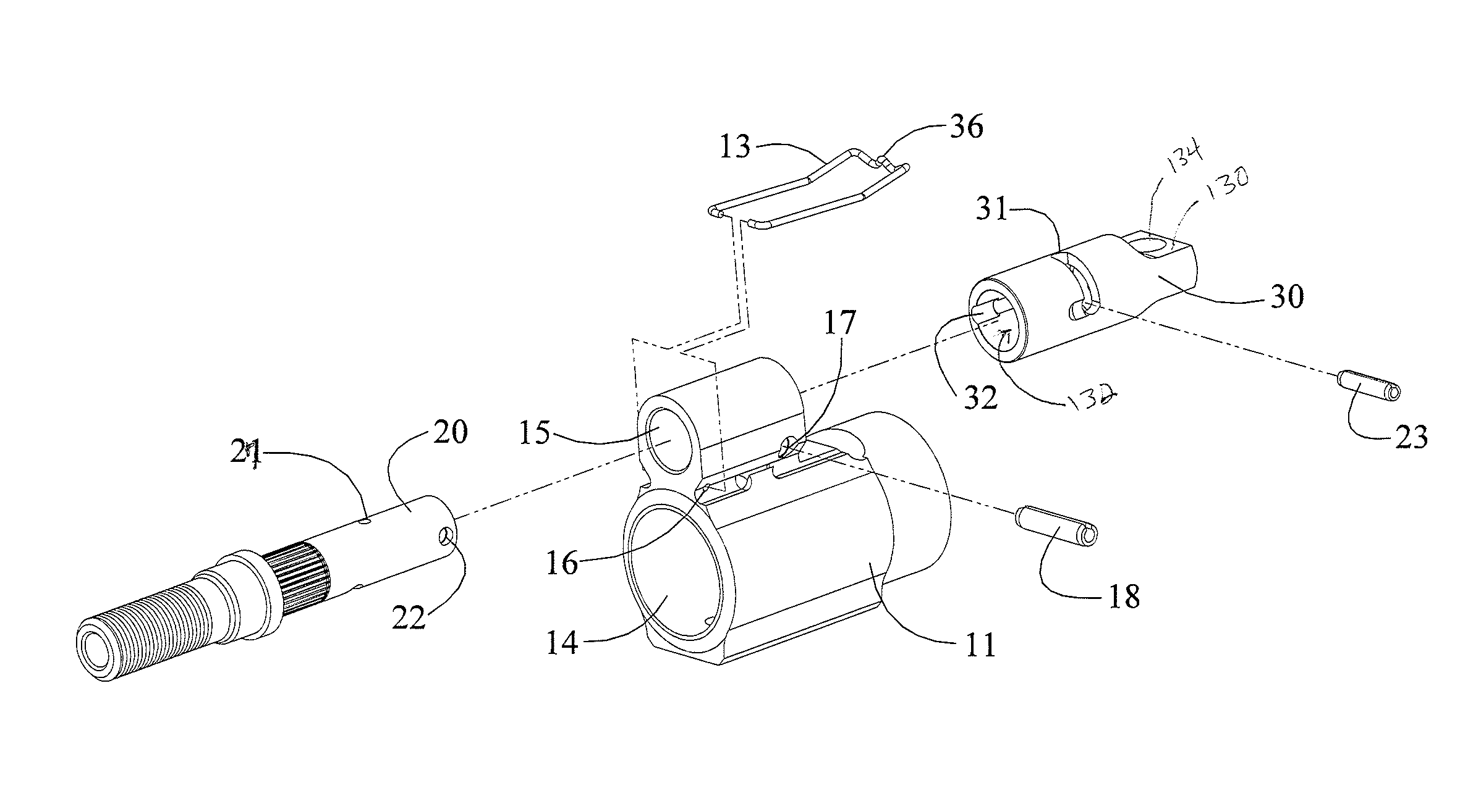
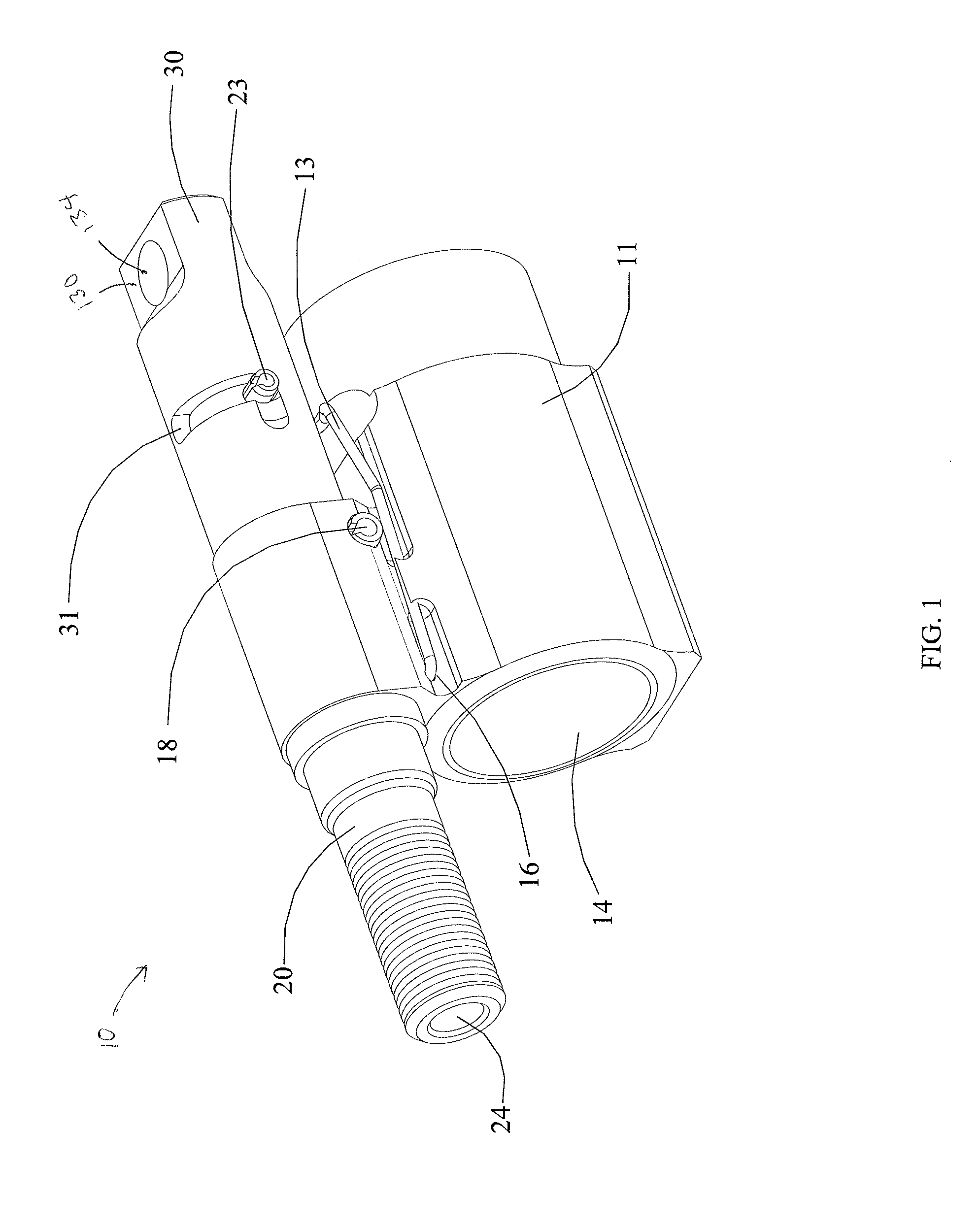
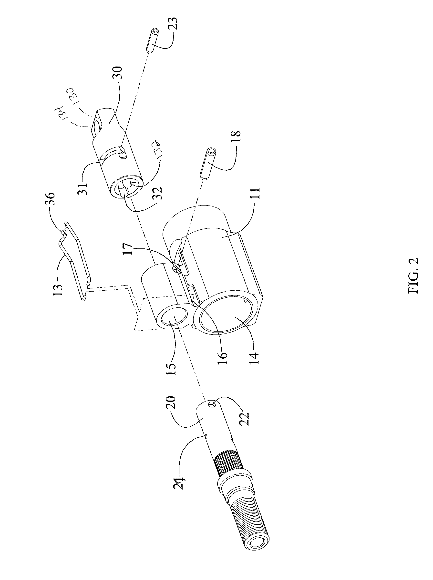
The present invention provides an adjustable gas block for a gas operated rifle that allows the user to easily select between two gas settings without the need for tools. The first position allows for a "standard" volume of gas to flow into the operating system, while the second position reduces the volume of gas which flows into the gas operating system by placing a channel and chamber located within the adjustment knob into communication with a secondary port located at the forward end of the gas nozzle. This allows the firearm's operating system to receive essentially the same volume of gas as it would in the absence of the noise suppressor. The adjustable gas block uses a fixed position gas nozzle and eliminates the need for a rotatable gas cylinder, which simplifies the design and reduces the likelihood of malfunctions.

Problems solved by technology

Unfortunately, due to varying lengths of barrels, ammunition variance, and other factors, it is very difficult to choose a gas port size which universally works under all conditions.
This extra gas, or back pressure, increases the firing rate of a weapon when operating at full auto, fouls the weapon leading to premature malfunction, can cause a variety of feeding and extraction problems, and causes premature wear on the reciprocating parts of the operating system.
Prior art designs typically rely on the use of tools to adjust the position of the gas cylinder, an inconvenient requirement for civilian, law enforcement and military users alike.
Further, many prior art designs are subject to carbon build up between the rotating gas cylinder and the gas block housing.
The carbon build up can cause the gas cylinder to become locked up, making rotation very difficult without frequent maintenance.

Method used


Image

  • Adjustable gas block for a gas operated firearm
  • Adjustable gas block for a gas operated firearm
  • Adjustable gas block for a gas operated firearm

Examples


Embodiment Construction

[0026]The adjustable gas block for a gas operated firearm in accordance with the present invention is designed to provide two positions of adjustment, each of which regulates the flow of gas between the barrel gas port and the indirect gas operating system, or operating system, of the host firearm.

[0027]Turning now to the drawings, in which like reference characters indicate corresponding elements throughout the several views, FIG. 1 shows an adjustable gas block, generally described by reference number 10, in accordance with the present invention. The adjustable gas block 10 is generally comprised of a housing 11, an adjustment knob 30, and a gas nozzle 20. In FIG. 1, the adjustment knob 30 is in the first position which provides an appropriate volume of gas for operating the host rifle 90, shown in FIGS. 5 and 9, when a back pressure generating device such as a noise suppressor or silencer is not being used.

[0028]As used herein, the word “front” or “forward” corresponds to the end...


PUM


Abstract

An adjustable gas block for a gas operated firearm offering a means to adjust a volume of gas directed to the host rifle's operating system. The adjustable gas block provides two positions of adjustment that are selectable based on the presence of a pressure increasing device being mounted on the firearm. A first position provides an optimal volume of gas into the gas operating system absent a back pressure increasing device. A second position usable in the presence of a back pressure increasing device causing venting of a portion of the volume of gas into a secondary chamber prior to release into the atmosphere. The amount of gas received by the operating system due to venting is reduced to a volume that is substantially equal to the volume of gas that would be received by the operating system absent a back pressure increasing device.

Description

BACKGROUND OF THE INVENTION[0001]1. Field of Invention[0002]This present invention generally relates to autoloading firearms, specifically to gas blocks for autoloading firearms which facilitate user adjustment to change the volume of gas that flows between the barrel and the operating system.[0003]2. Description of the Related Art[0004]The need to regulate the flow of gas between the barrel and operating system of a firearm has been a concern since the invention of autoloading firearms. Gas is generated during the combustion of gun powder present in the cartridges used in firearms. This gas expands violently to push the bullet out of the firearm's barrel. These expanding gases are also utilized as a means to operate the action of the host firearm. In modern firearms, the preferred method of facilitating the function of an autoloading weapon is as follows. A hole, or gas port, is placed through the barrel, generally on the top. Location of the gas port varies between operating syste...

Claims


Application Information

Patent Timeline
Patent Type & Authority Applications(United States)
IPC IPC(8): F41A5/18
CPCF41A5/18F41A5/28
Inventor GOMEZ, JESUS S.
Owner LWRC INTERNATIONAL
Learn More