
Method for treating hypertension via electrical stimulation of neural structures

a neural structure and electrical stimulation technology, applied in the field of tissue stimulation systems, can solve the problems of increasing the flow rate of blood, and increasing the burden on patients

Active Publication Date: 2014-03-20
BOSTON SCI NEUROMODULATION CORP
View PDF1 Cites 18 Cited by
  • Summary
  • Abstract
  • Description
  • Claims
  • Application Information

AI Technical Summary

Benefits of technology

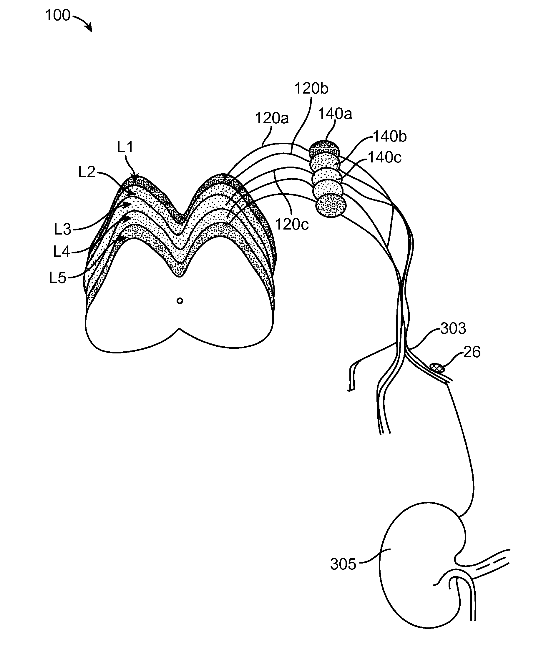
The present invention provides a system and method for treating chronic hypertension by applying electrical modulation energy to a neural target site to modulate an afferent nerve fiber innervating a kidney of a patient. This results in the reduction of blood pressure in the patient. The system includes a sensor, modulation output circuitry, and a controller / processor for comparing the sensed parameter to a threshold and instructing the modulation output circuitry to convey the electrical modulation energy to the electrode. The method involves applying electrical modulation energy to the target site on the afferent nerve fiber, which may be epidurally or transcutaneously, and the patient may have a blood pressure greater than 140 mm Hg systolic / 90 mm Hg diastolic prior to the application of the modulation energy. The invention provides a non-invasive and effective treatment for chronic hypertension.

Problems solved by technology

Hypertension is a health problem affecting millions of people, requiring considerable expenditure of medical resources as well as imposing significant burdens on those who suffer from this condition.
Because blood vessels do not permit easy flow, the patient's heart must pump at higher pressure.
In addition, reduced cross-sectional area results in higher flow velocity.
Electrical energy, operating at radio frequencies, is applied to the electrode, resulting in destruction of the renal nerves.
This process, of course, is irreversible and carries the possibility of undesirable side effects.

Method used


Image

  • Method for treating hypertension via electrical stimulation of neural structures
  • Method for treating hypertension via electrical stimulation of neural structures
  • Method for treating hypertension via electrical stimulation of neural structures

Examples


Embodiment Construction

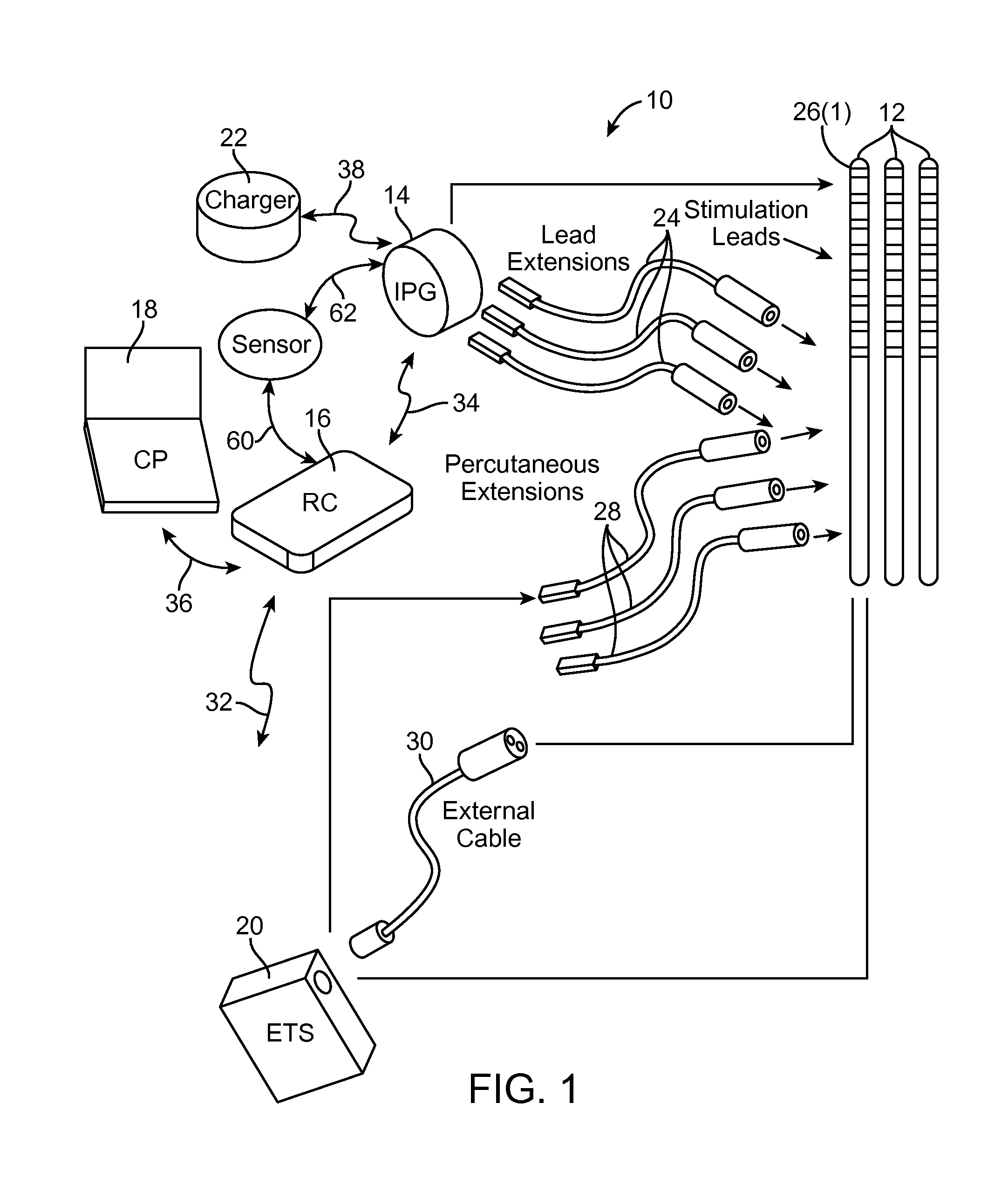
[0023]Turning first to FIG. 1, an exemplary neuromodulation system 10 generally comprises a plurality of modulation leads 12 (in this case, three), an implantable pulse generator (IPG) 14 (or alternatively RF receiver-stimulator), an external remote control (RC) 16, a Clinician's Programmer (CP) 18, an External Trial Stimulator (ETS) 20, and an external charger 22.

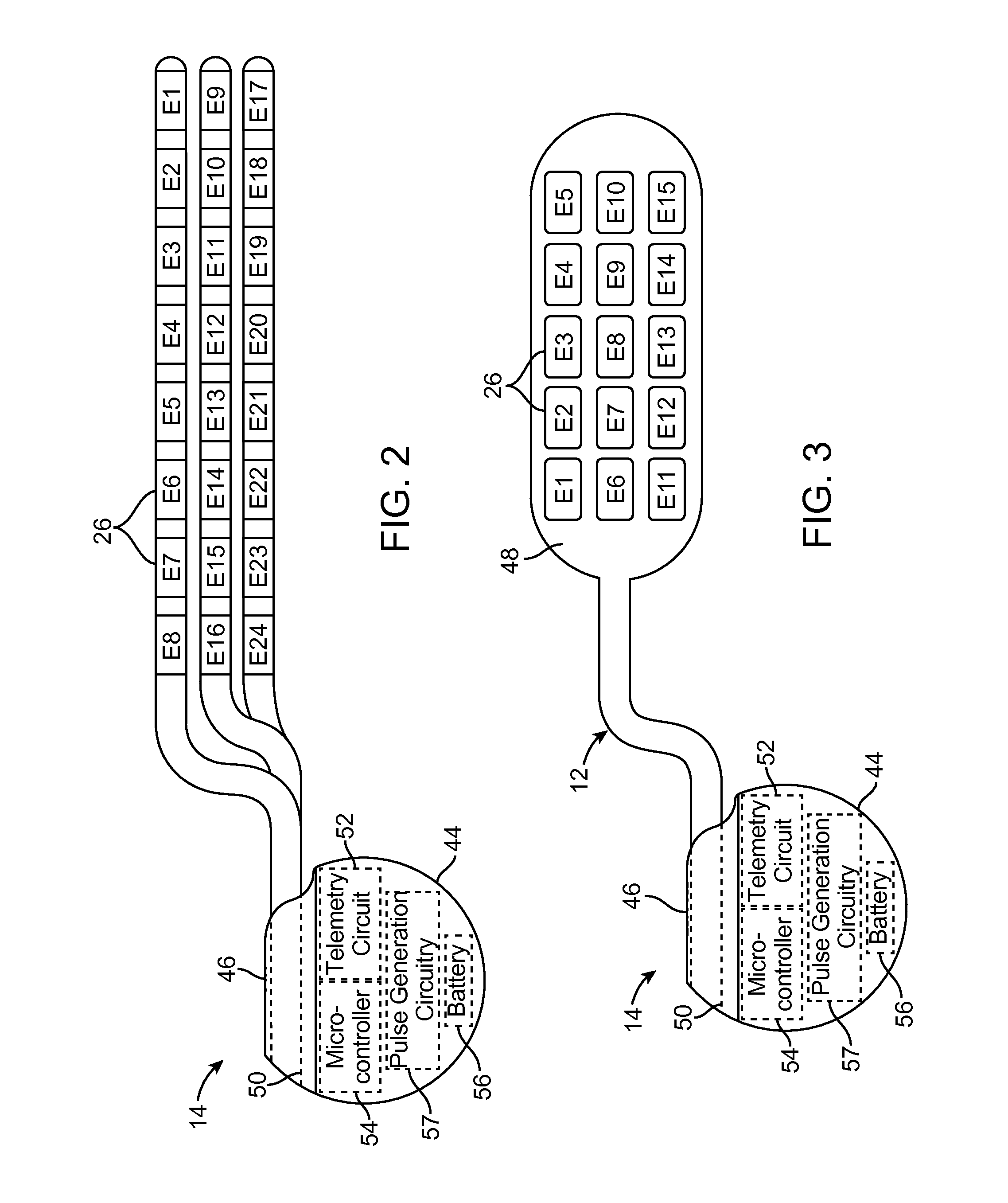
[0024]The IPG 14 is physically connected via one or more lead extensions 24 to the modulation leads 12, which carry a plurality of electrodes 26 arranged in an array. The modulation leads 12 are illustrated as percutaneous leads in FIG. 1, although as will be described in further detail below, a surgical paddle lead can be used in place of the percutaneous leads. As will also be described in further detail below, the IPG 14 includes pulse generation circuitry (FIG. 2) that delivers electrical modulation energy in the form of a pulsed electrical waveform (i.e., a temporal series of electrical pulses) to the array of electro...


PUM


Abstract

A neuromodulation system comprises a sensor configured for sensing a blood pressure of a patient, modulation output circuitry configured for conveying electrical modulation energy to at least one electrode, and a controller / processor coupled to the sensor and the modulation output circuitry. The controller / processor is configured for comparing the blood pressure sensed by the sensor to a first threshold blood pressure, and instructing the modulation output circuitry to convey the electrical modulation energy to the at least one electrode if the sensed blood pressure is greater than the first threshold blood pressure. A method for treating chronic hypertension comprises applying electrical modulation energy to a neural target site, thereby modulating an afferent nerve innervating a patient's kidney, thereby treating the chronic hypertension.

Description

RELATED APPLICATION DATA[0001]The present application claims the benefit under 35 U.S.C. §119 to U.S. provisional patent application Ser. No. 61 / 703,609, filed Sep. 20, 2012. The foregoing application is hereby incorporated by reference into the present application in its entirety.FIELD OF THE INVENTION[0002]The present invention relates to tissue stimulation systems, and more particularly, to electrical stimulation systems for treating hypertension in patients.BACKGROUND OF THE INVENTION[0003]Implantable neurostimulation systems have proven therapeutic in a wide variety of diseases and disorders. For example, Spinal Cord Stimulation (SCS) techniques, which directly stimulate the spinal cord tissue of the patient, have long been accepted as a therapeutic modality for the treatment of chronic neuropathic pain syndromes, and the application of spinal cord stimulation has expanded to include additional applications, such as angina pectoralis, peripheral vascular disease, and incontinen...

Claims


Application Information

Patent Timeline
Patent Type & Authority Applications(United States)
IPC IPC(8): A61N1/36
CPCA61N1/36117A61N1/0551A61N1/36A61N1/36007
Inventor HERSHEY, BRADLEY L.
Owner BOSTON SCI NEUROMODULATION CORP
Learn More