Floating offshore wind turbine with tuned mass dampers

a wind turbine and mass damper technology, which is applied in the direction of marine propulsion, vessel parts, vessel construction, etc., can solve the problems of wind turbines that have a tendency to destabilize, affect the dynamic response, and compromise the structural integrity of both the buoyancy structure and the tower, so as to achieve better control

Inactive Publication Date: 2014-03-20
GE RENEWABLE TECH WIND BV
View PDF3 Cites 16 Cited by
  • Summary
  • Abstract
  • Description
  • Claims
  • Application Information

AI Technical Summary

Benefits of technology

[0017]In some embodiments each tuned mass damping configuration may comprise a plurality of tuned mass dampers. The plurality of tuned mass dampers of each tuned mass damping configuration may have a center of gravity along the line where the respective tuned mass damping configuration is arranged. When a plurality of tuned mass dampers is employed as part of a mass damping configuration smaller masses are required to dampen the same amount of force and the harmonics of the oscillations are better controlled.
[0018]In some embodiments each tuned mass damping configuration may further comprise a container for enclosing the one or more tuned mass dampers. The container may be attached to the nacelle support structure and each tuned mass damper may be attached to the inner walls of the container. Such a container may protect the tuned mass damper from corrosion.

Problems solved by technology

In the presence of such loads floating wind turbines may have a tendency to destabilize.
On the one hand, these types of buoyancy structures are subject to relatively large displacements at the tower base (surge, sway, heave), which may affect the dynamic response of the nacelle-rotor-assembly due to elevated accelerations.
On the other hand, they are subject to relatively large rotations (roll, pitch, yaw) at the tower base, which may compromise the structural integrity of both the buoyancy structure and the tower, with the danger of ultimate collapse.
The aforementioned loads may cause a FOWT to oscillate.
However, these solutions increase material significantly.
As the weight of the buoyancy structure goes up, so does the cost of manufacture and installation.
Nevertheless, these strategies have limited effect and can only mitigate oscillations resulting from some specific forces (not all).

Method used


Image

  • Floating offshore wind turbine with tuned mass dampers
  • Floating offshore wind turbine with tuned mass dampers
  • Floating offshore wind turbine with tuned mass dampers

Examples


Embodiment Construction

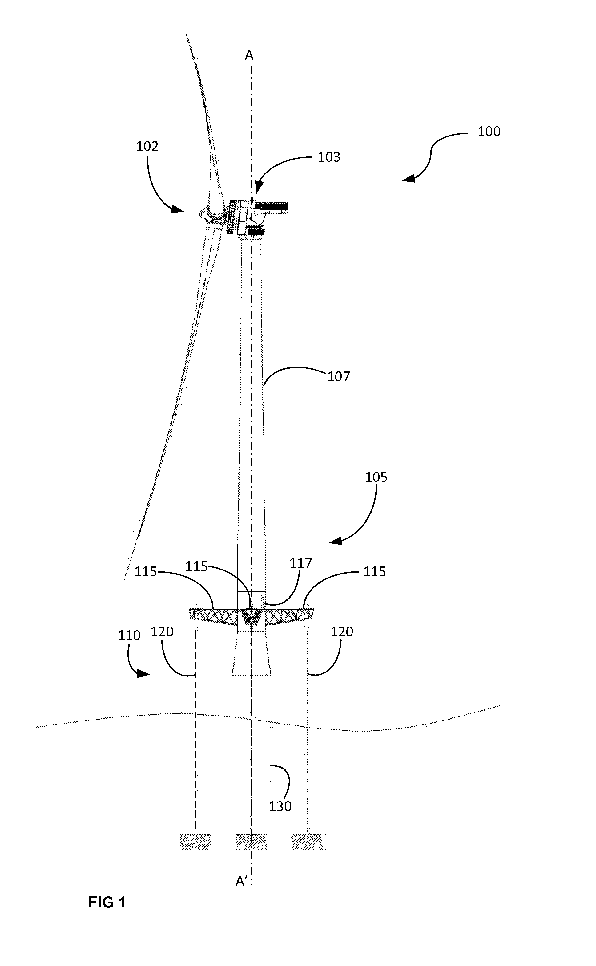
[0038]FIG. 1 shows a floating offshore wind turbine, and more particularly a floating wind turbine of the TLP (Tension Leg Platform) type.

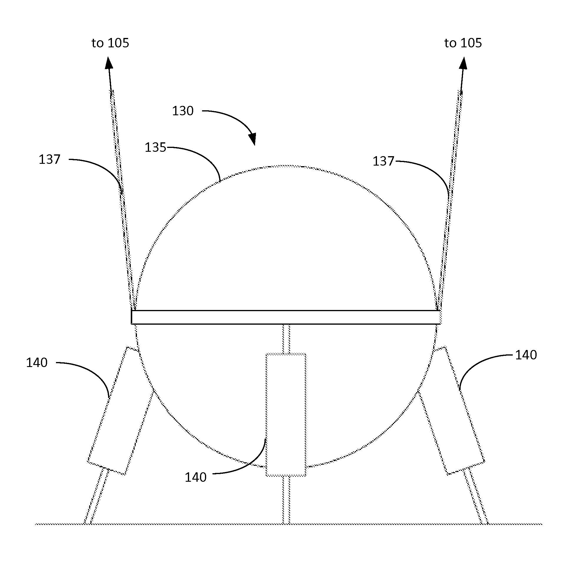
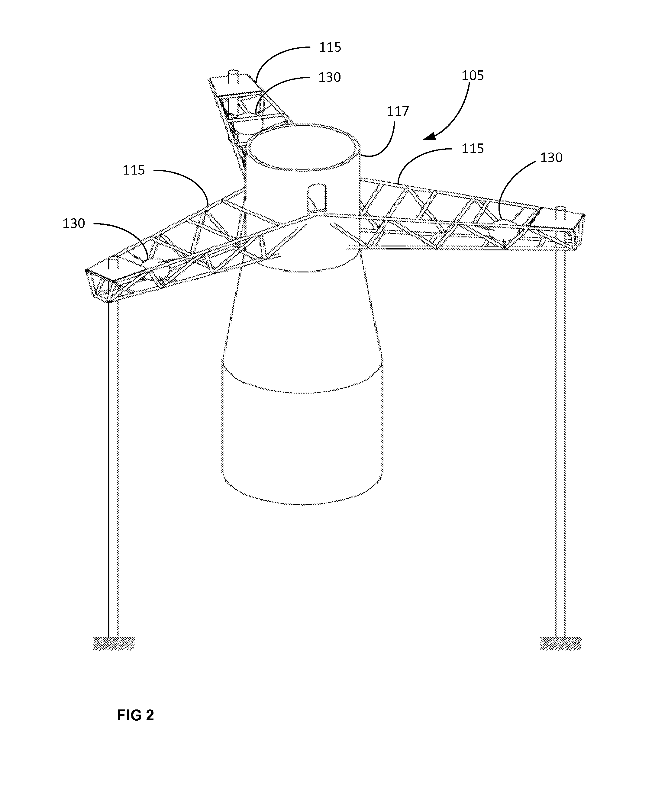
[0039]The offshore wind turbine 100 comprises rotor 102 having a plurality of blades, nacelle 103 and nacelle support structure 105. Nacelle support structure comprises wind turbine tower 107 and buoyancy structure 110, with at least one floater tank 130. Nacelle support structure 105 has a central longitudinal axis A-A′.

[0040]The buoyancy structure 110 may be designed such as to remain submerged in a position above the sea bed SB and below the mean sea level MSL, to provide an upward thrust for supporting the weight of the wind turbine and other loads. The floater tank 130 may have a substantially cylindrical shape, such as shown in FIG. 1, and may have a diameter that is smaller than its length. For example, the floater tank 130 may be around 20 m in length and have a diameter of between 6 and 12 m. This kind of buoyancy structures are sometimes...


PUM


Abstract

A floating offshore wind turbine comprises a rotor with a plurality of blades, a nacelle and a nacelle support structure having a central longitudinal axis. A plurality of tuned mass damping configurations is arranged around the central longitudinal axis of the nacelle support structure to dampen vibrations in all 6 degrees of freedom.

Description

[0001]This application claims the benefit of European Patent Application No. 12382359.3 filed on Sep. 17, 2012 and U.S. Provisional Patent Application Ser. No. 61 / 728,115 filed on Nov. 19, 2012, the disclosures of which are hereby incorporated by references in their entirety for all purposes.[0002]The present invention relates to floating offshore wind turbines.BACKGROUND ART[0003]Offshore wind turbines are being developed that instead of resting on fixed-bottom support structures have a floating support structure.[0004]Several configurations have been proposed for the floating or buoyancy structures: many of these employ floater elements in the form of hollow floater tanks that in use are arranged substantially below the mean sea level and provide a buoyancy force to support the wind turbine. Ballast and / or mooring lines anchored to the seabed are provided for achieving stability.[0005]In some of these floating wind turbines, the buoyancy structure is designed to provide an excess ...

Claims


Application Information

Patent Timeline
Patent Type & Authority Applications(United States)
IPC IPC(8): F03D11/04
CPCF03D11/04F05B2240/93F05B2250/33F05B2260/96F03D80/00F03D13/25B63B21/502B63B39/005B63B2035/446Y02E10/727E02B17/0004E02B2017/0091Y02E10/72F16F7/10
Inventor RODRIGUEZ TSOUROUKDISSIAN, ARTURO
Owner GE RENEWABLE TECH WIND BV
Why Eureka
Try Eureka