Eureka AIR delivers breakthrough ideas for toughest innovation challenges, trusted by R&D personnel around the world.

Stepped electrode assembly having predetermined a thickness ratio in the interface between electrode units, battery cell and device comprising the same

a technology of electrode unit and thickness ratio, which is applied in the direction of wound/folded electrode electrodes, batteries, sustainable manufacturing/processing, etc., can solve the problems of limited design freedom, large design restrictions, and degradation of shape freedom, so as to maintain the capacitance and durability characteristics, the design freedom is very superior, and the effect of dead spa

Active Publication Date: 2014-03-13
LG ENERGY SOLUTION LTD
View PDF6 Cites 69 Cited by
  • Summary
  • Abstract
  • Description
  • Claims
  • Application Information

AI Technical Summary

Benefits of technology

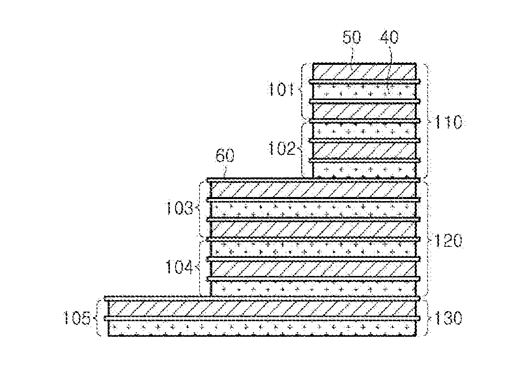
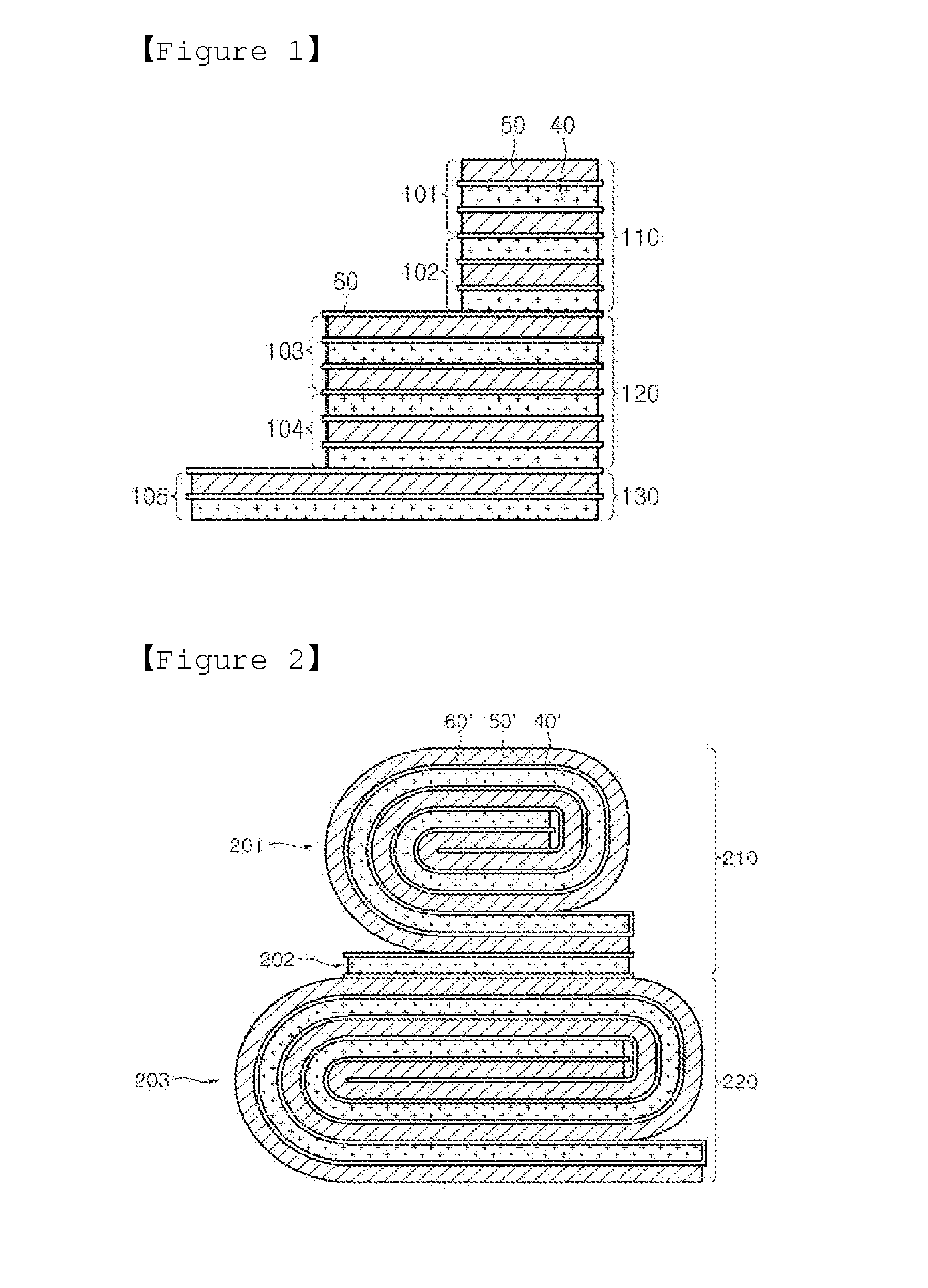
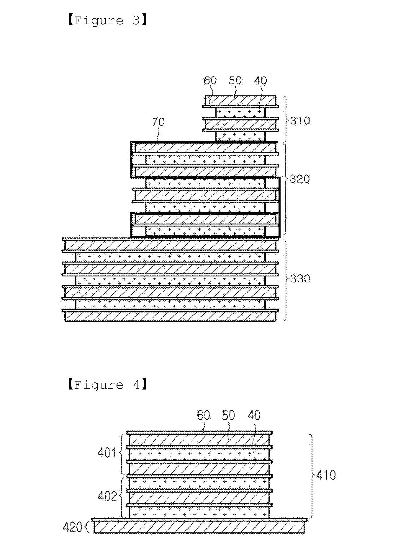
The present invention provides an electrode assembly with various designs that are thinner and have excellent electrical capacity. This design allows for better space utilization in electric devices. The electrode assembly has a balance between the positive and negative electrodes at the interface between electrode units with different areas. This results in better durability and capacitance while minimizing dead space. The design freedom of the electrode assembly is also superior.

Problems solved by technology

However, the related art electrode assemblies known to date are generally fabricated in a manner of stacking unit cells or individual electrodes having the same size, degrading a degree of freedom in shape, to result in a great deal of design restrictions.
At this time, since the area in each stepped portion is controllable but the thickness of the stepped portion is limited to multiples of the thickness of each stepped portion, the design freedom in designing the thickness direction of the batteries is limited.
Also, the above-described existing techniques only propose ideas that may change the design by cutting negative electrode plates and positive electrode plates to have desired sizes to form unit cells having different sizes, and stacking the cut negative electrode plates and the cut positive electrode plates, and do not propose a concrete method that may allow a battery having battery characteristics that are actually usable to be manufactured.
For example, in the case of a battery having a stepped portion, although each unit cell constituting the battery and having a different size operates without error, it is common that the battery cannot actually be used, due to problems in which it is impossible to operate these batteries according to the configuration of unit cells constituting each stepped portion when the electrodes are stacked, battery capacitance is remarkably low compared to other batteries having the same volume, or severe swelling occurs at an interface between stepped portions, thus severely shortening product lifespan.
However, these existing batteries having a stepped portion are not configured in consideration of the above-described problem.

Method used


Image

  • Stepped electrode assembly having predetermined a thickness ratio in the interface between electrode units, battery cell and device comprising the same
  • Stepped electrode assembly having predetermined a thickness ratio in the interface between electrode units, battery cell and device comprising the same
  • Stepped electrode assembly having predetermined a thickness ratio in the interface between electrode units, battery cell and device comprising the same

Examples


manufacturing example 1

Positive Electrode A

[0154]LiCoO2 was used as a positive electrode active material and polyvinylidene fluoride (PVDF) was used as a binder, the positive electrode active material and the binder were dissolved in N-methyl-2-pyrrolidone (NMP) and then mixed to prepare a positive electrode paste. The positive electrode paste was coated on both surfaces of an aluminum foil collector having a thickness of 15 μm, dried in an oven at 150° C., and pressed to manufacture a positive electrode A. The manufactured positive electrode A had a thickness of 100 μm, a porosity of 21%, and a reversible capacitance of 335 mAh.

manufacturing example 2

Positive Electrode B

[0155]A positive electrode B was manufactured using the same method as that in Manufacturing Example 1 except that the thickness of the positive electrode became 110 μm. The manufactured positive electrode B had a thickness of 110 μm, a porosity of 21%, and a reversible capacitance of 375 mAh.

manufacturing example 3

Negative Electrode A

[0156]A blend material of natural graphite and artificial graphite was used as a negative electrode active material, and styrene-butadiene rubber (SBR) and carboxymethyl cellulose (CMC) carbon were used as a binder. The negative electrode active material and the binder were dissolved in distilled water and mixed to prepare a negative electrode paste. After the negative electrode paste thus obtained was coated on both surfaces of a copper foil collector having a thickness of 10 μm, the copper foil collector coated with the paste was thermally treated in an oven at 100° C., and pressed to manufacture a negative electrode A. The manufactured negative electrode A had a thickness of 105 μm, a porosity of 27%, and a reversible capacitance of 348 mAh.


PUM


Abstract

There are provided an electrode assembly, and a battery cell, a battery pack, and a device. The electrode assembly includes a combination of two or more types of electrode units having different areas, wherein the electrode units are stacked such that steps are formed, and electrode units are formed such that a positive electrode and a negative electrode face one another at an interface between the electrode units.

Description

CROSS-REFERENCE TO RELATED APPLICATIONS[0001]This application is a continuation of International Application No. PCT / KR2013 / 002142, filed Mar. 15, 2013, which claims the benefit of Korean Application Nos. 10-2012-0041474, filed Apr. 20, 2012, 10-2012-0125636, filed Nov. 7, 2012, 10-2012-127013, filed Nov. 9, 2012, 10-2013-0014722, filed Feb. 8, 2013, and 10-2013-0028288, filed Mar. 15, 2013 in the Korean Intellectual Property Office, the disclosures of which are incorporated herein by reference.FIELD OF THE INVENTION[0002]The present invention relates to an electrode assembly, and a battery cell and a device comprising the same, and more particularly, to an electrode assembly including a combination of two or more types of electrode units having different areas, in which the electrode units are stacked such that steps are formed, a positive electrode and a negative electrode face at an interface between the electrode units.BACKGROUND OF THE INVENTION[0003]Recently, due to the techno...

Claims


Application Information

Patent Timeline
IPC IPC(8): H01M10/04H01M10/052H01M10/0565H01M10/0585H01M10/0587H01M50/103H01M50/528H01M50/529
CPCH01M10/0431H01M10/0436H01M10/0463H01M10/0525H01M10/0583H01M10/0585H01M2004/021H01M10/052H01M10/0587H01M50/103Y02P70/50Y02E60/10H01M2220/30H01M50/531H01M50/105H01M2220/20H01M2220/10Y02T10/70H01M10/0413H01M50/46H01M2300/0082H01M50/533H01M50/20H01M2010/4292H01M2004/028H01M2004/027H01M50/529
Inventor KWON, SUNG-JINAHN, SOON-HOKIM, DONG-MYUNGKIM, KI-WOONGKIM, YOUNG-HOONYOON, SUNG-HANRYU, SEUNG-MIN
Owner LG ENERGY SOLUTION LTD
Why Eureka
Eureka Blog
Learn More