Method of manufacturing heat dissipating base, heat dissipating base and heat dissipating device

a technology heat dissipating base, which is applied in the direction of indirect heat exchangers, laminated elements, light and heating apparatus, etc., can solve the problems of significant performance issues of heat dissipating device, electrical components may get damaged due to accumulated heat, and current in circuit will generate unnecessary heat. , to achieve the effect of large thermal conductivity, small thermal conductivity and large thermal conductivity

Inactive Publication Date: 2014-03-13
COOLER MASTER DEVELOPMENT CORP
View PDF10 Cites 1 Cited by
  • Summary
  • Abstract
  • Description
  • Claims
  • Application Information

AI Technical Summary

Benefits of technology

[0010]As mentioned in the above, the first heat conducting material (i.e. the first base) with large thermal conductivity is covered by the second heat conducting material (i.e. the second base) with small thermal conductivity in the die casting process, so as to form the heat dissipating base. After forming the heat dissipating base, the first base with large thermal conductivity is located at the center of the heat dissipating base and the upper and lower surfaces thereof are exposed. The first base of the heat dissipating device can be attached to an electronic component, such that heat generated by the electronic component can be conducted to the heat dissipating members on the heat dissipating base through the first base. For example, the invention may use copper with large thermal conductivity to form the first base and use aluminum with small thermal conductivity to form the second base, so as to reduce the manufacturing cost of the heat dissipating base effectively.

Problems solved by technology

When an electronic product is operating, the current in circuit will generate unnecessary heat due to impedance.
If the heat is accumulated in the electronic components of the electronic product without dissipating immediately, the electronic components may get damage due to the accumulated heat.
Therefore, the performance of heat dissipating device is a significant issue for the electronic product.
In general, the electronic component is always attached to the center of the copper base, such that the periphery of the copper base does not work well on heat dissipation.
If the whole base is made of copper only, the manufacturing cost of the heat dissipating device will increase.

Method used


Image

  • Method of manufacturing heat dissipating base, heat dissipating base and heat dissipating device
  • Method of manufacturing heat dissipating base, heat dissipating base and heat dissipating device
  • Method of manufacturing heat dissipating base, heat dissipating base and heat dissipating device

Examples


first embodiment

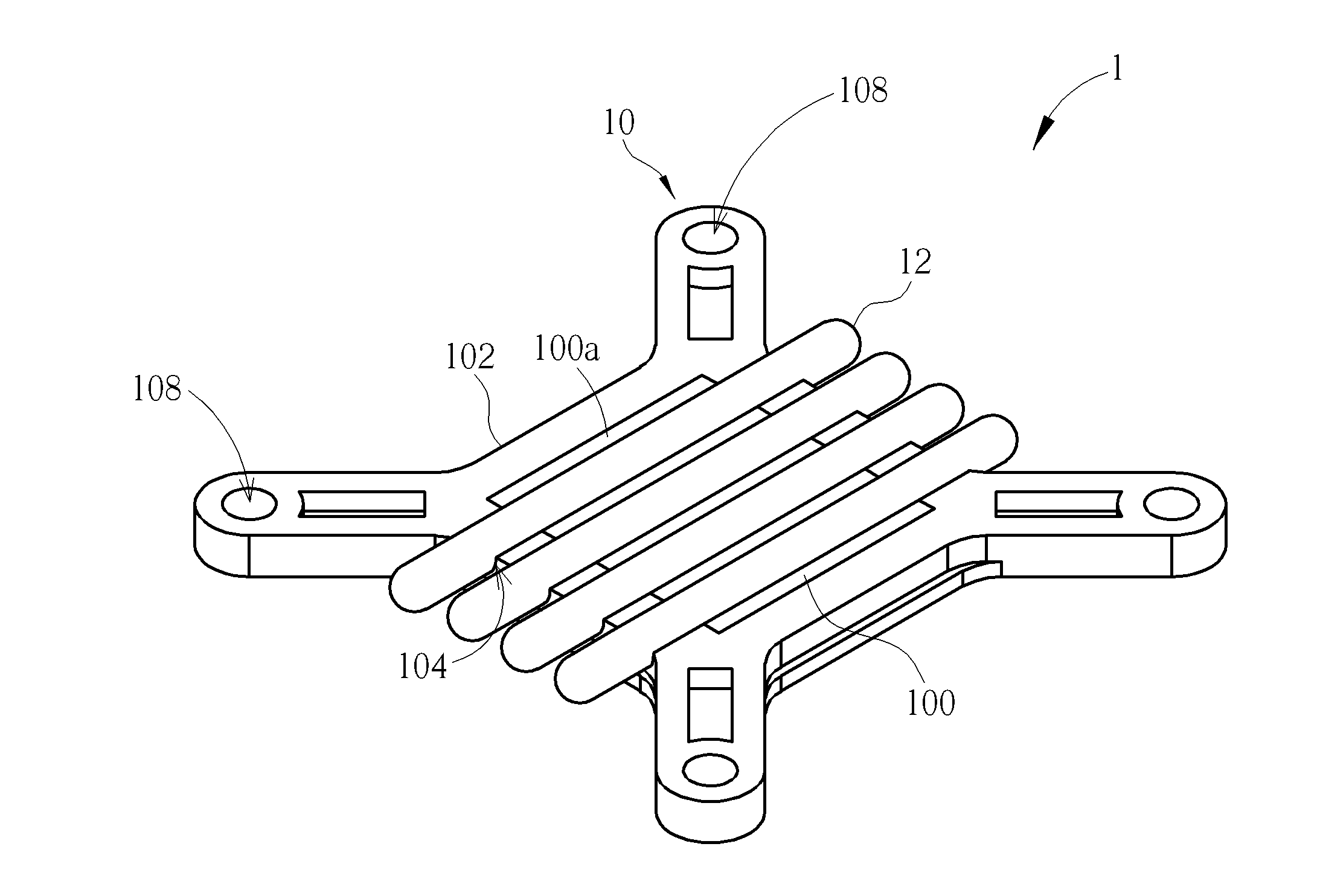
[0020]Referring to FIGS. 1 to 6, FIG. 1 is a schematic view illustrating a heat dissipating device 1 according to the invention, FIG. 2 is a schematic view illustrating the heat dissipating base 10 shown in FIG. 1, FIG. 3 is a schematic view illustrating the heat dissipating base 10 shown in FIG. 2 in another viewing angle, FIG. 4 is a cross-sectional view illustrating the heat dissipating base 10 along line X-X shown in FIG. 2, FIG. 5 is an exploded view illustrating the heat dissipating base 10 shown in FIG. 2, and FIG. 6 is an exploded view illustrating the heat dissipating base 10 shown in FIG. 3. As shown in FIG. 1, the heat dissipating device 1 comprises a heat dissipating base 10 and a plurality of heat dissipating members 12, wherein the heat dissipating members 12 are disposed on the heat dissipating base 10. In this embodiment, the heat dissipating members 12 are heat pipes.

[0021]As shown in FIGS. 1 to 6, the heat dissipating base 10 comprises a first base 100 and a second...

second embodiment

[0025]Referring to FIG. 8 along with FIG. 1, FIG. 8 is a schematic view illustrating a heat dissipating device 1′ according to the invention. The difference between the heat dissipating device 1′ and the aforesaid heat dissipating device 1 is that the heat dissipating base 10 of the heat dissipating device 1′ does not has the aforesaid fixing grooves 104 and the heat dissipating members 12 are heat dissipating fins fixed on the first base 100. For example, the heat dissipating members 12 may be fixed on the first base 100 by soldering, engaging structures or other fixing manners or, alternatively, the heat dissipating members 12 may be formed with the first base 100 integrally by the die casting process according to practical applications. It should be noted that the same elements in FIG. 8 and FIGS. 1 to 6 are represented by the same numerals, so the repeated explanation will not be depicted herein again.

[0026]Compared with the prior art, the first heat conducting material (i.e. th...


PUM

PropertyMeasurementUnit
heat conductingaaaaaaaaaa
thermal conductivityaaaaaaaaaa
heat dissipatingaaaaaaaaaa

Abstract

A method of manufacturing a heat dissipating base includes steps of providing a first base, wherein the first base is made of a first heat conducting material; putting the first base into a mold; pouring a second heat conducting material, which is melted, into the mold, wherein a thermal conductivity of the first heat conducting material is larger than that of the second heat conducting material; and processing the second heat conducting material by a die casting process, so as to form a second base, wherein the second base covers a periphery of the first base and an upper surface and a lower face of the first base are exposed.

Description

BACKGROUND OF THE INVENTION[0001]1. Field of the Invention[0002]The invention relates to a method of manufacturing a heat dissipating base, a heat dissipating base and a heat dissipating device and, more particularly, to a heat dissipating base formed by a die casting process using two heat conducting materials with different thermal conductivities.[0003]2. Description of the Prior Art[0004]Heat dissipating device is a significant component for electronic products. When an electronic product is operating, the current in circuit will generate unnecessary heat due to impedance. If the heat is accumulated in the electronic components of the electronic product without dissipating immediately, the electronic components may get damage due to the accumulated heat. Therefore, the performance of heat dissipating device is a significant issue for the electronic product.[0005]In a conventional heat dissipating device, heat pipes or heat dissipating fins are disposed a copper base and the coppe...

Claims


Application Information

Patent Timeline
Patent Type & Authority Applications(United States)
IPC IPC(8): B23P15/26F28F3/02
CPCF28F3/02B23P15/26B22D19/0072B22D19/04F28D15/0275F28F3/06F28F2013/006F28F2255/146H01L23/4006H01L23/427H01L2924/0002Y10T29/4935H01L2924/00
Inventor LIN, CHIA-YU
Owner COOLER MASTER DEVELOPMENT CORP
Why Eureka
Try Eureka