
Transformer having assembled bobbins and voltage transformation module having the transformer

a transformer and transformer technology, applied in the field of transformers, can solve the problems of increasing the temperature after, affecting the performance of the transformer, and affecting the efficiency of the transformer, so as to reduce the heat accumulation in the bobbins, prevent the heat accumulation between the adjacent bobbin and the secondary winding, and facilitate air convection

Active Publication Date: 2014-03-06
CHICONY POWER TECH CO LTD
View PDF11 Cites 6 Cited by
  • Summary
  • Abstract
  • Description
  • Claims
  • Application Information

AI Technical Summary

Benefits of technology

This design enhances heat dissipation and reduces temperature accumulation, providing a more efficient cooling mechanism while allowing for flexible transformer sizing without the need for multiple bobbin and casing designs.

Problems solved by technology

However, since the interior of the bobbin of the conventional transformer is an axial channel, an electric current or an induced current flowing the electric leads inevitably generates heat, and the heat will be accumulated inside the bobbin (i.e. in the axial channel).
Such a problem of heat accumulation is more serious in a large-power transformer such as a 600-watt transformer.
Since the conventional transformer is not provided with any heat-dissipating means, the heat accumulated inside the bobbin will cause the increase in its temperature after being operated for a period of time.
Even, the performance of the transformer may be deteriorated by the rising temperature.
However, both ends of the bobbin are blocked by the magnetic cores, so that the airflow generated by such an external fan can only blow the outer surface of the bobbin, but cannot dissipate the heat accumulated inside the bobbin.
As a result, the manufacturer has to spend a lot of money to design various molds for this purpose, which increases the production cost.
However, such a conventional transformer having combined bobbins does not solve the problem of heat accumulation in the bobbin.

Method used


Image

  • Transformer having assembled bobbins and voltage transformation module having the transformer
  • Transformer having assembled bobbins and voltage transformation module having the transformer
  • Transformer having assembled bobbins and voltage transformation module having the transformer

Examples


Embodiment Construction

[0035]The detailed description and technical contents of the present invention will become apparent with the following detailed description accompanied with related drawings. It is noteworthy to point out that the drawings is provided for the illustration purpose only, but not intended for limiting the scope of the present invention.

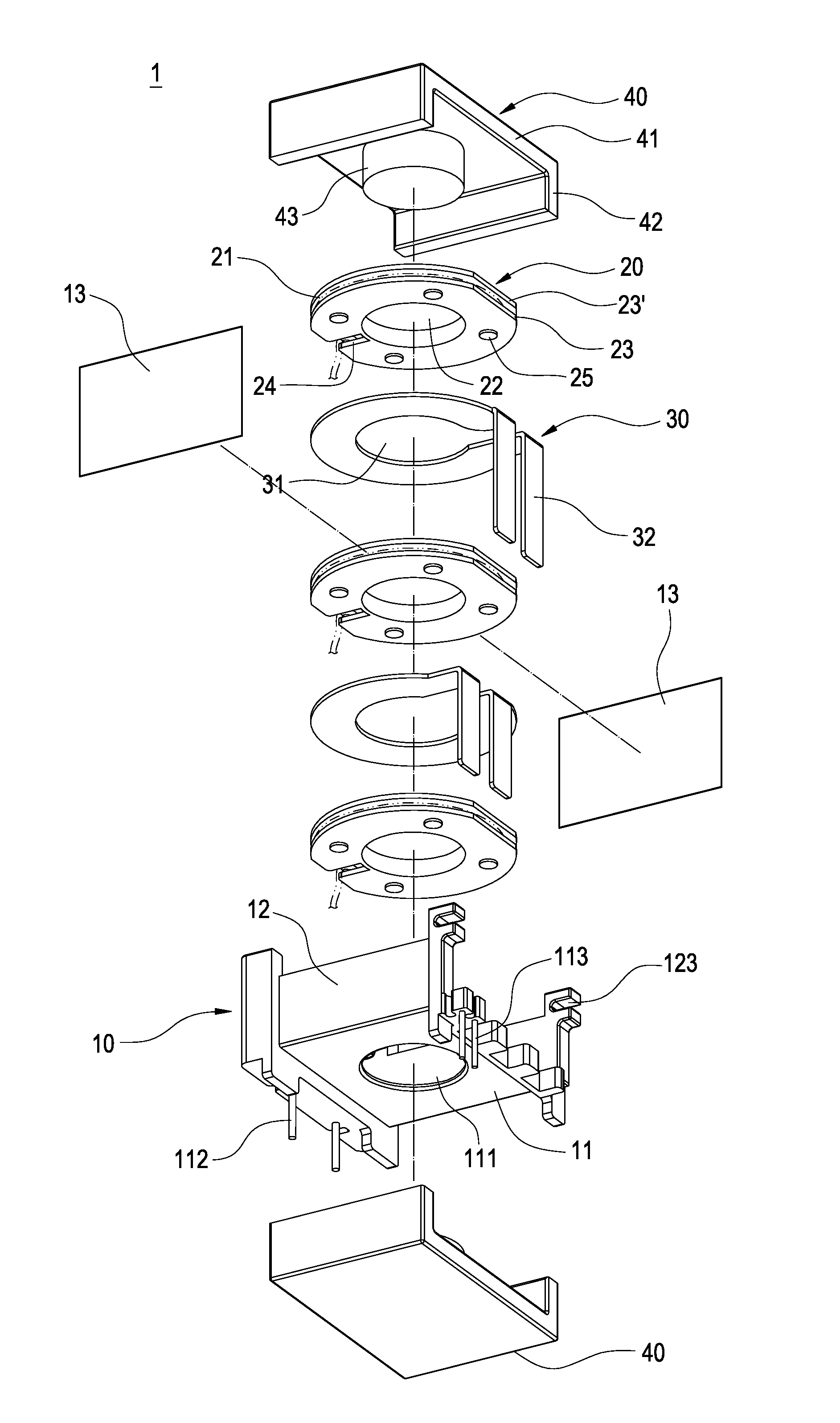
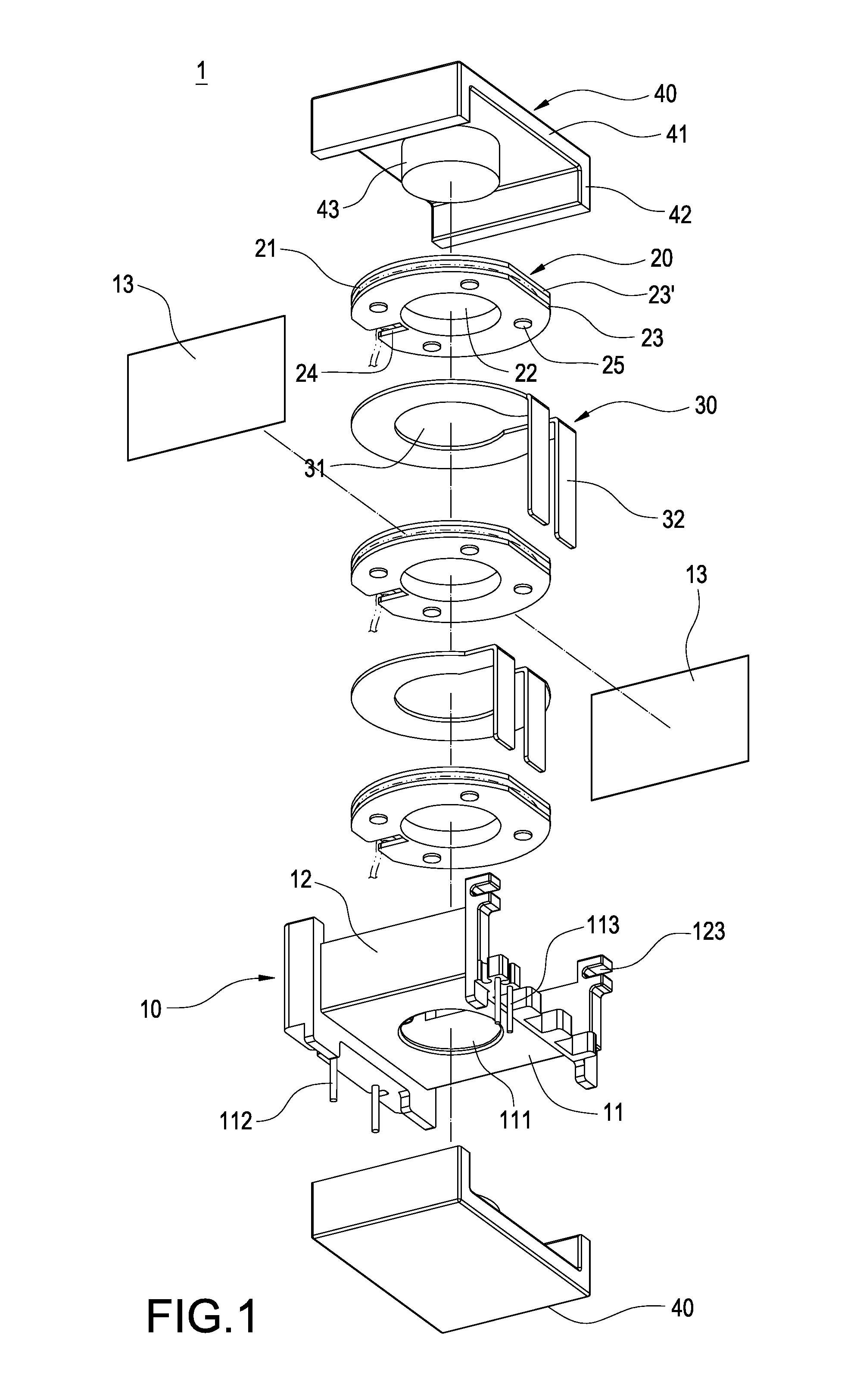
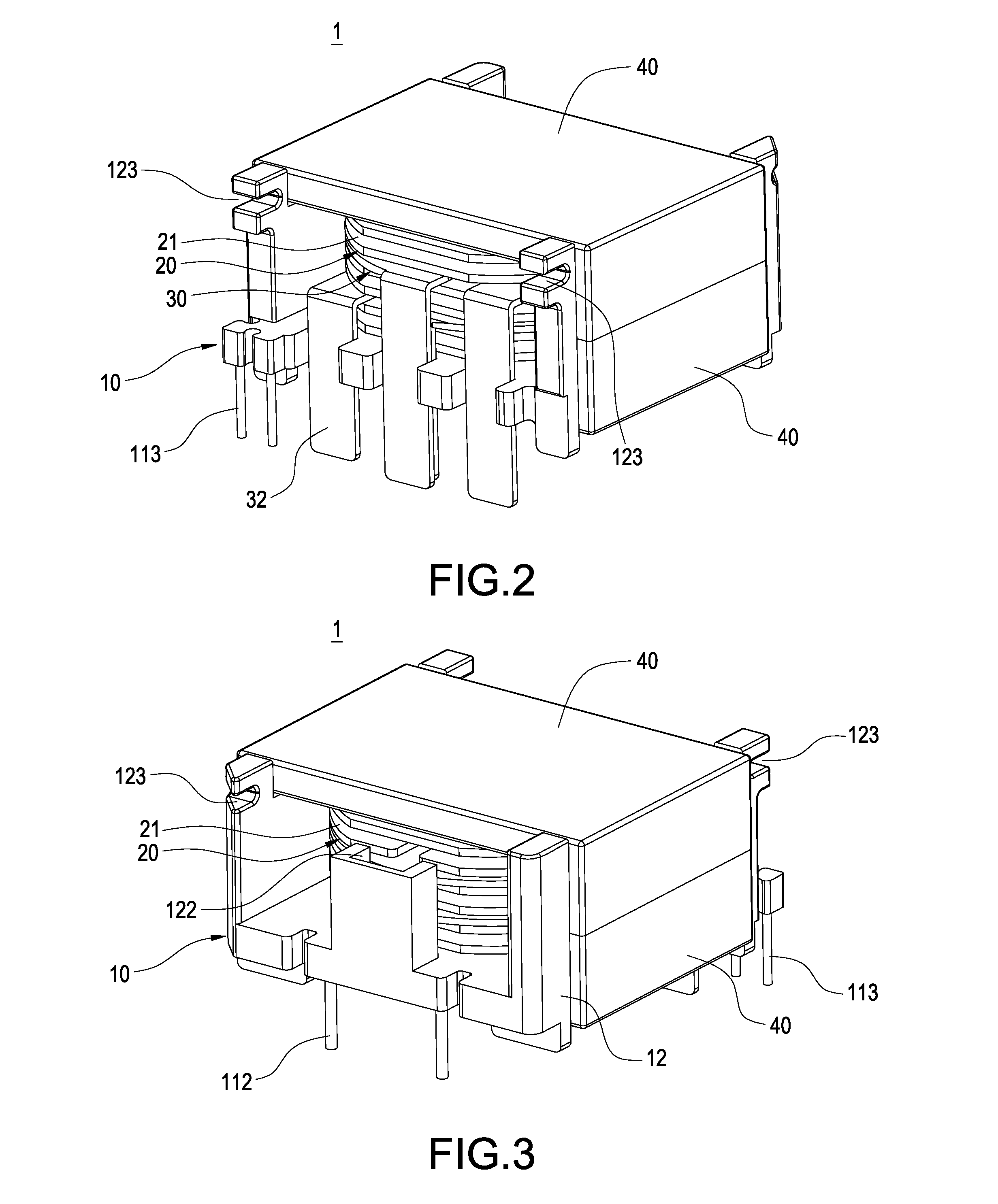
[0036]Please refer to FIGS. 1 to 6. The present invention provides a transformer 1 having assembled bobbins, which includes a base 10, a plurality of bobbins 20, a plurality of secondary windings 30, and two magnetic cores 40.

[0037]The base 10 includes a bottom plate 11 and two side plates 12 vertically extending from both sides of the bottom plate 11, respectively. The bottom plate 11 is provided with a penetration hole 111 as well as a plurality of first pins 112 and a plurality of second pins 113. Further, on two edges of the bottom plate 11 different from the two side plates 12, the bottom plate 11 of the base 10 is provided with a first groove 122 (...


PUM

PropertyMeasurementUnit
magneticaaaaaaaaaa
electrical conductiveaaaaaaaaaa
outer diameteraaaaaaaaaa

Abstract

The present invention provides a transformer having assembled bobbins and a voltage transformation module having the transformer. The transformer includes a base, bobbins, secondary windings and two magnetic cores. The base is provided with a penetration hole. The bobbins are disposed in the base and each has an annular groove, a hollow portion corresponding to the penetration hole, and protrusions formed on a surface of the bobbin. The protrusions form a gap between the two adjacent bobbins when the two adjacent bobbins are assembled with each other. The secondary windings are disposed between the bobbins and each has a through-hole corresponding to the hollow portion. The two magnetic cores penetrate the penetration hole of the base, the hollow portions of the bobbins, and the through-holes of the secondary windings to assemble them together.

Description

CROSS-REFERENCE[0001]This application is a continuous application of U.S. patent application Ser. No. 13 / 540,930, filed Jul. 3, 2012.BACKGROUND OF THE INVENTION[0002]1. Field of the Invention[0003]The present invention relates to a transformer, and in particular to a transformer having assembled bobbins and a voltage transformation module having the transformer.[0004]2. Description of Related Art[0005]A transformer is an electronic component in which magnetic cores, primary windings and secondary windings are provided to generate electromagnetic induction for converting voltage. The conventional transformer includes a bobbin and two magnetic cores. The bobbin is formed into a hollow cylindrical shape and has an axial channel. Both ends of the bobbin extend to form a plurality of pins. Two sets of electric leads are wound around both ends of the bobbin adjacent to its corresponding pin in different turn numbers, thereby forming a primary winding and a secondary winding respectively. ...

Claims


Application Information

Patent Timeline
Patent Type & Authority Applications(United States)
IPC IPC(8): H01F27/08
CPCH01F27/085H01F27/2866H01F27/306
Inventor HSU, HAO-TEHSIAO, YUNG-HUNG
Owner CHICONY POWER TECH CO LTD
Learn More